Electromagnetic valve and method for manufacturing the same

a technology of electromagnetic valves and valve bodies, which is applied in the direction of valve operating means/release devices, magnetic bodies, brake systems, etc., can solve the problems of electromagnetic valves becoming larger in size and generating electromagnetic noise in pressure sensors, so as to achieve the effect of shortening the manufacturing tim

Inactive Publication Date: 2009-01-01
ADVICS CO LTD
View PDF22 Cites 19 Cited by
  • Summary
  • Abstract
  • Description
  • Claims
  • Application Information

AI Technical Summary

Benefits of technology

[0007]According to the above feature of the present invention, since the magnetic flux flow to the sensor is suppressed by the magnetic flux limiting portion, generation of magnetic noise in the sensor is reduced even when the sensor and the coil are arranged closer to each other. Accordingly, precise detection at the sensor can be achieved and at the same time the electromagnetic valve can be made smaller in its size.
[0008]Furthermore, the magnetic flux, which is suppressed from flowing toward the sensor, flows through the armature. As a result, the performance of the electromagnetic valve (for example, response, attracting force, etc.) is improved.
[0009]According to another feature of the invention, the magnetic flux limiting portion is formed by a groove formed at an outer peripheral surface of the stator core. According to the above feature of the invention, since the magnetic flux limiting portion is formed by the groove, which can be manufactured by the cutting process, the magnetic flux limiting portion can be more easily formed in the stator core when compared with a case in that the magnetic flux limiting portion is formed by the heating and cooling process. This is because a crack is likely to be generated in the material for the stator core during a process of rapid heating and rapid cooling.
[0013]According to such a method, since the portion of the stator core is heated by the laser radiation, it is easy to heat a narrow area which should be non-magnetized. In addition, a manufacturing time can be made shorter, when compared with the case in which the groove is formed by the cutting process to form the magnetic flux limiting portion.
[0014]According to a still further feature of the invention, a method of manufacturing the electromagnetic valve has a step for winding a different metal of non-magnetic material around an outer periphery of the stator core, the different metal being different from a metal for the stator core; and a step for melting the different metal and a base material of the stator core to form the magnetic flux limiting portion. According to such a method, it is easy to form the magnetic flux limiting portion in the stator core, which is made of such a material that is not non-magnetized by heating process.
[0016]According to a still further feature of the invention, the different metal and the base material of the stator core are molten by heat of laser radiation in the above method of manufacturing the electromagnetic valve. According to this feature, a manufacturing time can be made shorter, when compared with the case in which the groove is formed by the cutting process to form the magnetic flux limiting portion.

Problems solved by technology

This is because the pressure may not be precisely detected, as a result that electromagnetic noise is generated in the pressure sensor in the case that the pressure sensor is arranged at a position closer to the electromagnetic coil and electric current is supplied to the electromagnetic coil.
Accordingly, it is a problem that the electromagnetic valve may become larger in its size.

Method used


Image

  • Electromagnetic valve and method for manufacturing the same
  • Electromagnetic valve and method for manufacturing the same
  • Electromagnetic valve and method for manufacturing the same

Examples


first embodiment

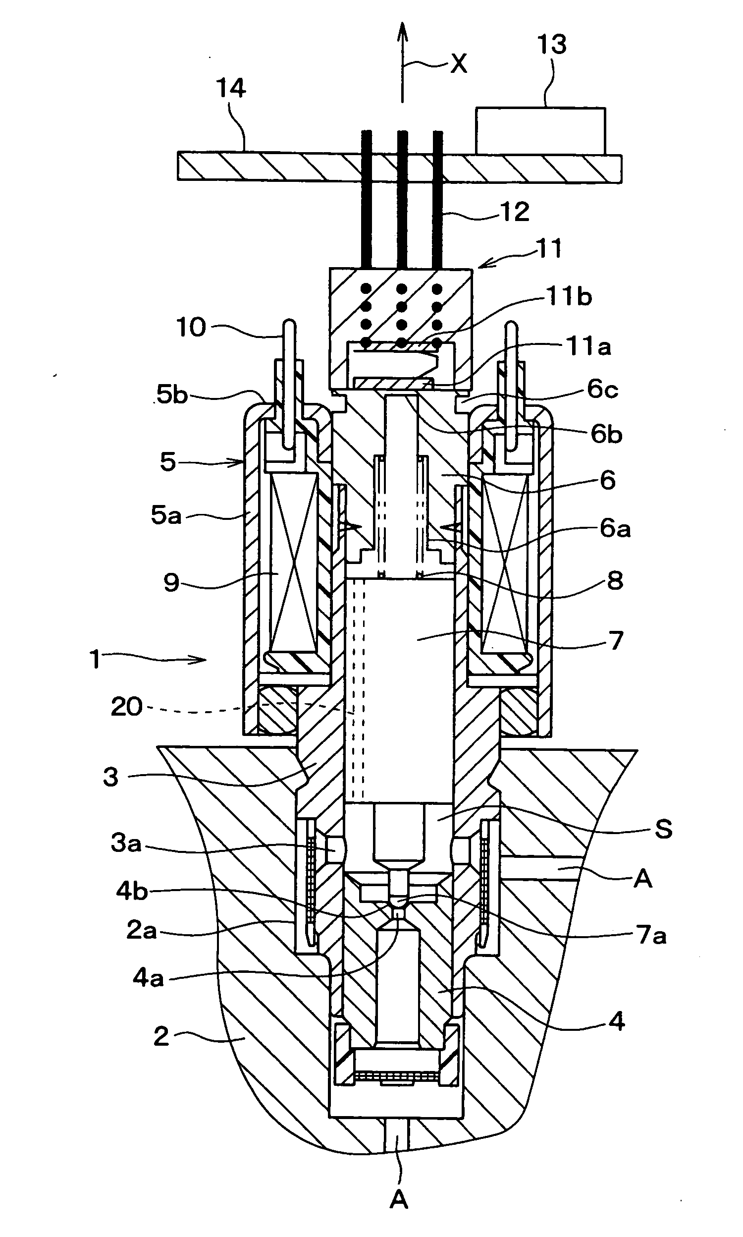
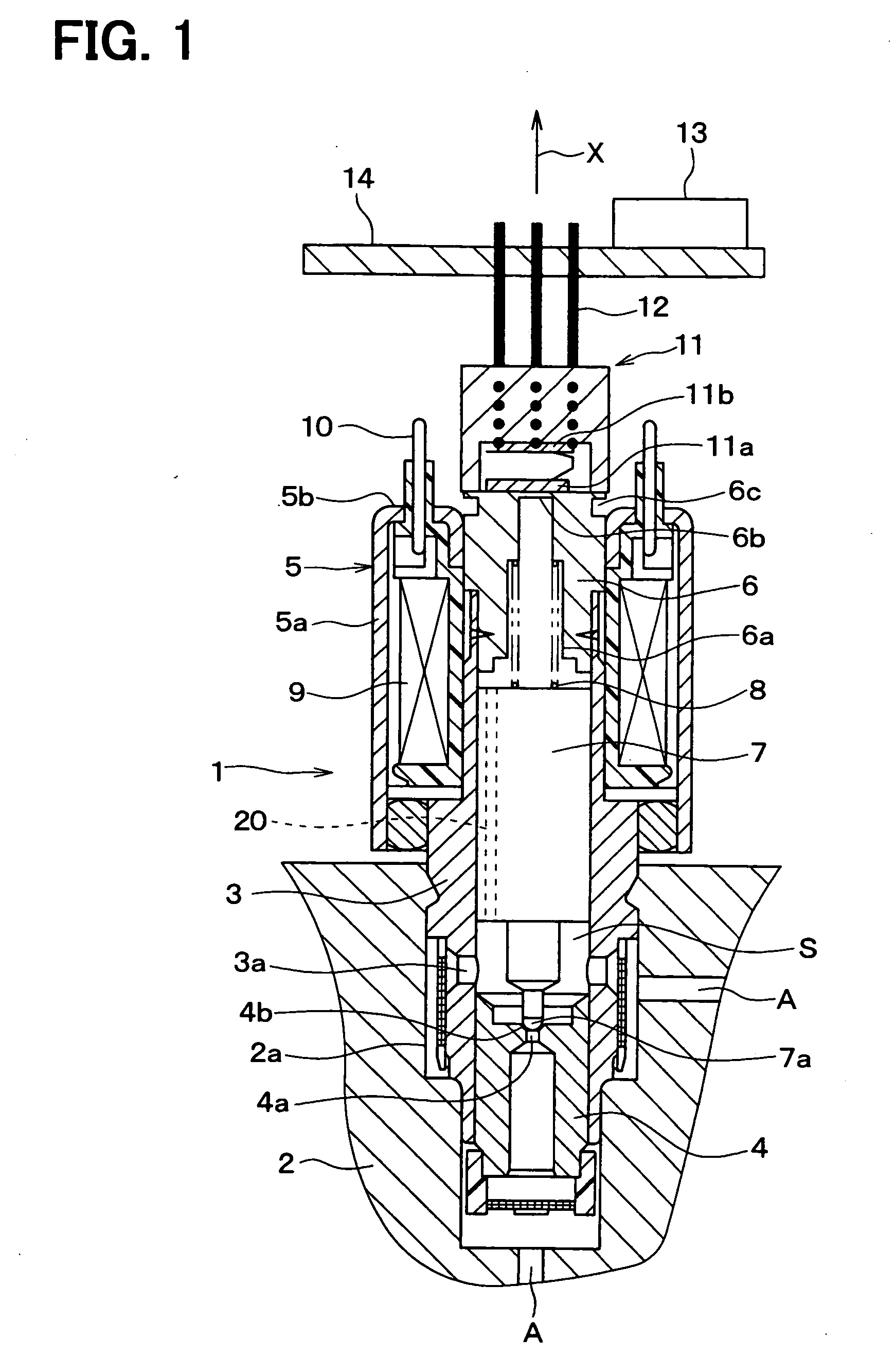
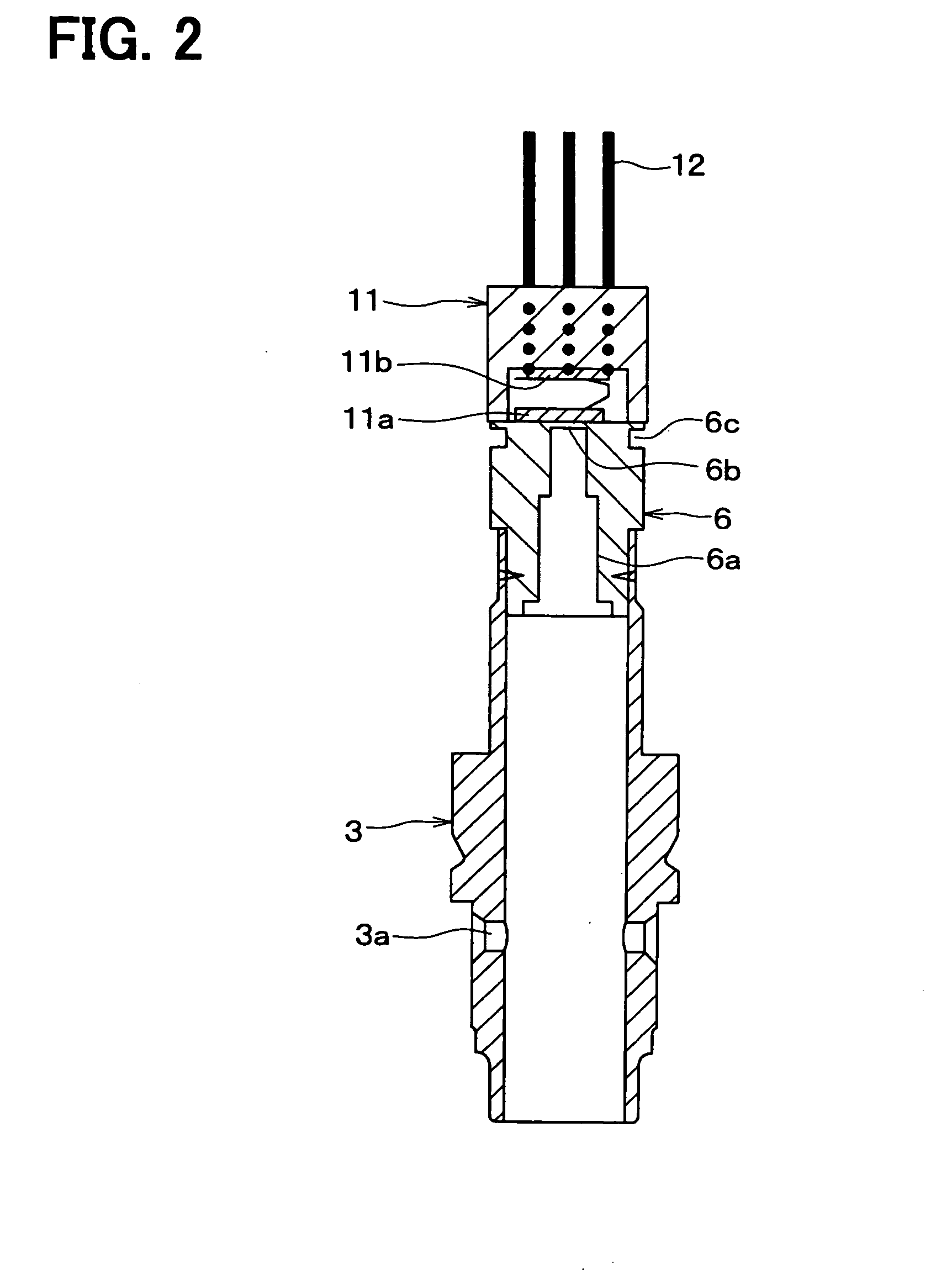
[0024]A first embodiment of the present invention will be hereinafter explained with reference to the drawings. FIG. 1 is a cross sectional view showing an entire structure of an electromagnetic valve 1 according to a first embodiment of the present invention. And FIG. 2 is a cross sectional view showing a sleeve 3, a stator core 6, and a pressure sensor 11.

[0025]The electromagnetic valve 1 is arranged in a fluid passage A for brake fluid, which is for example formed in a housing 2 of a vehicle ABS (anti-lock braking system) actuator. The electromagnetic valve 1 is used as a control valve for brake fluid to close and / or open the fluid passage A in accordance with current supply condition to an electromagnetic coil 9.

[0026]The electromagnetic valve 1 has a sleeve 3 of a cylindrical shape, which is formed of a composite magnetic metal. A portion of the sleeve 3, which is positioned at an inner periphery of the electromagnetic coil 9 (explained below), is heat treated so that such port...

second embodiment

[0046]A second embodiment of the present invention will be explained. FIG. 3 is a cross sectional view showing a major portion of an electromagnetic valve according to a second embodiment of the present invention. According to the embodiment, a portion of the stator core 6 is non-magnetized to form the magnetic flux limiting portion 6c. The other portions are the same to those of the first embodiment.

[0047]The stator core 6 of the second embodiment is made of magnetic metal, such as martensitic stainless steel. A portion of the stator core 6 is heated by laser radiation and then cooled down, so that martensite is changed to austenite (namely non-magnetized). More exactly, the heat of the portion which is heated by the laser radiation is absorbed by base material surrounding the heated portion after the termination of the laser radiation, so that such heated and cooled down portion is non-magnetized. Such non-magnetized portion forms the magnetic flux limiting portion 6c. And at leas...

third embodiment

[0050]A third embodiment of the present invention will be explained FIGS. 4A and 4B are cross sectional views showing a major portion of an electromagnetic valve according to the third embodiment of the present invention. According to the embodiment, a portion of the stator core 6 is non-magnetized to form the magnetic flux limiting portion 6c. The other portions are the same to those of the first embodiment.

[0051]The stator core 6 of this embodiment is made of magnetic metal, such as Nickel alloy metal. More exactly, the metal, which has the same or almost the same coefficient of linear expansion to that of the sensing gauge 11a mainly made of silicon, is used as the material for the stator core 6.

[0052]A non-magnetic metal foil 15 of a different metal from the stator core 6 is wound around an outer periphery of the stator core 6, as shown in FIG. 4A, in order to non-magnetize a portion of the stator core 6. Then, laser radiation is carried out at such portion, at which the non-mag...


PUM

PropertyMeasurementUnit
magnetic fieldaaaaaaaaaa
magnetic fluxaaaaaaaaaa
non-magneticaaaaaaaaaa

Abstract

An electromagnetic valve has an electromagnetic coil supported by a cylindrical yoke, a movable armature within a sleeve, a stator core fixed to one end of the sleeve, wherein one end of the stator core protrudes from an end of the yoke. A pressure sensor is attached to a protruding end of the stator core. A magnetic flux limiting portion is formed in the stator core at such a position which is on a side of the protruding end of the stator core toward the pressure sensor. A magnetic flux flow to the pressure sensor is limited by the magnetic flux limiting portion, so that a precise detection by the sensor can be achieved even when the sensor is arranged closer to the electromagnetic coil.

Description

CROSS REFERENCE TO RELATED APPLICATION[0001]This application is based on Japanese Patent Application No. 2007-167574 filed on Jun. 26, 2007 and No. 2008-044051 filed on Feb. 26, 2008, the disclosures of which are incorporated herein by reference.FIELD OF THE INVENTION[0002]The present invention relates to an electromagnetic valve, to which a sensor is integrally assembled, and a method for manufacturing such electromagnetic valve.BACKGROUND OF THE INVENTION[0003]An electromagnetic valve integrally having a sensor is known in the art, for example, Japanese Patent Publication No. 2005-351410, in which a pressure sensor is attached to an end surface of a stator core.[0004]In the conventional electromagnetic valve, however, the pressure sensor is arranged at such a substantial distance from an electromagnetic coil. This is because the pressure may not be precisely detected, as a result that electromagnetic noise is generated in the pressure sensor in the case that the pressure sensor is...

Claims


Application Information

Patent Timeline
Patent Type & Authority Applications(United States)
IPC IPC(8): F16K31/06B21K1/20
CPCF16K31/0675Y10T29/49412B60T8/363H01F7/081Y10T137/8326Y10T137/8242
Inventor MURAYAMA, TAKASHI
Owner ADVICS CO LTD
Why Eureka
Try Eureka