Master-slave type flip-flop circuit

a flip-flop circuit and masterslave technology, applied in the field of masterslave type flip-flop circuits, can solve the problems of increasing emi noise and noise amount, and achieve the effect of simplifying wiring and reducing power consumption and emi

Inactive Publication Date: 2009-01-01
SEIKO EPSON CORP
View PDF0 Cites 51 Cited by
  • Summary
  • Abstract
  • Description
  • Claims
  • Application Information

AI Technical Summary

Benefits of technology

[0041]According to thus configured present invention, reduction in power consumption and EMI can be planned in the case of being realized with a gate array.
[0042]In addition, according to the invention, a basic cell can be utilized effectively at the occasion of forming various kinds of logic circuits and, moreover, can be planned to secure wiring resource to simplify wiring in the case of being realized with a gate array.

Problems solved by technology

Therefore, in the case where a pass-through current is significant and the current change amount thereof is significant, noise amount due to EMI (electromagnetic interference) will become significant, giving rise to failure.
In addition, in the case where a pass-through current is significant and a current change amount (dI / dt) per unit time is significant, the EMI noise amount increases, giving rise to failure.

Method used


Image

  • Master-slave type flip-flop circuit
  • Master-slave type flip-flop circuit
  • Master-slave type flip-flop circuit

Examples


first embodiment

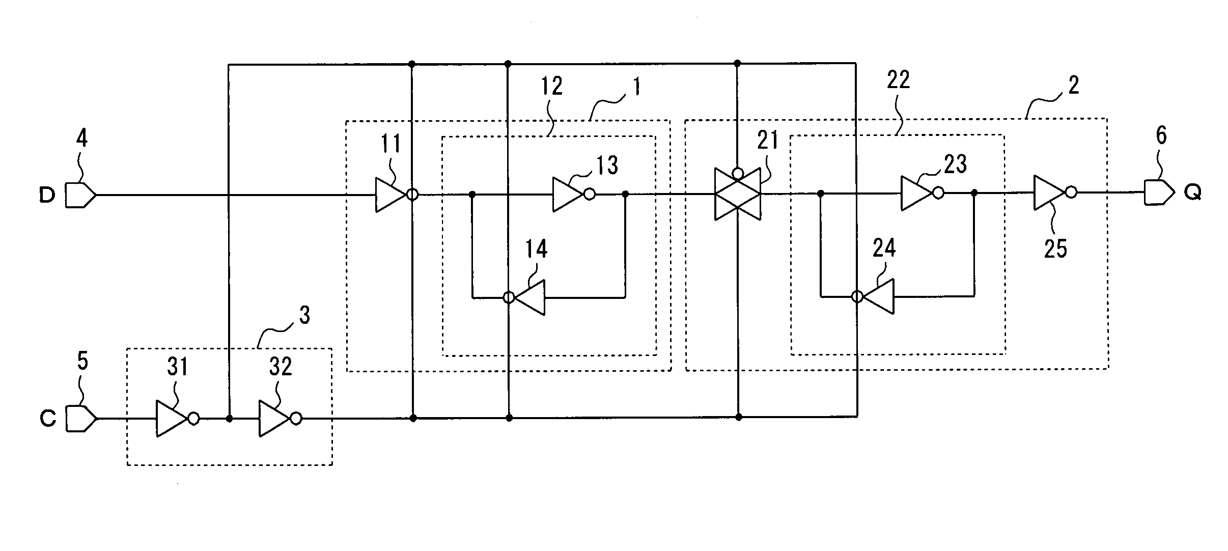
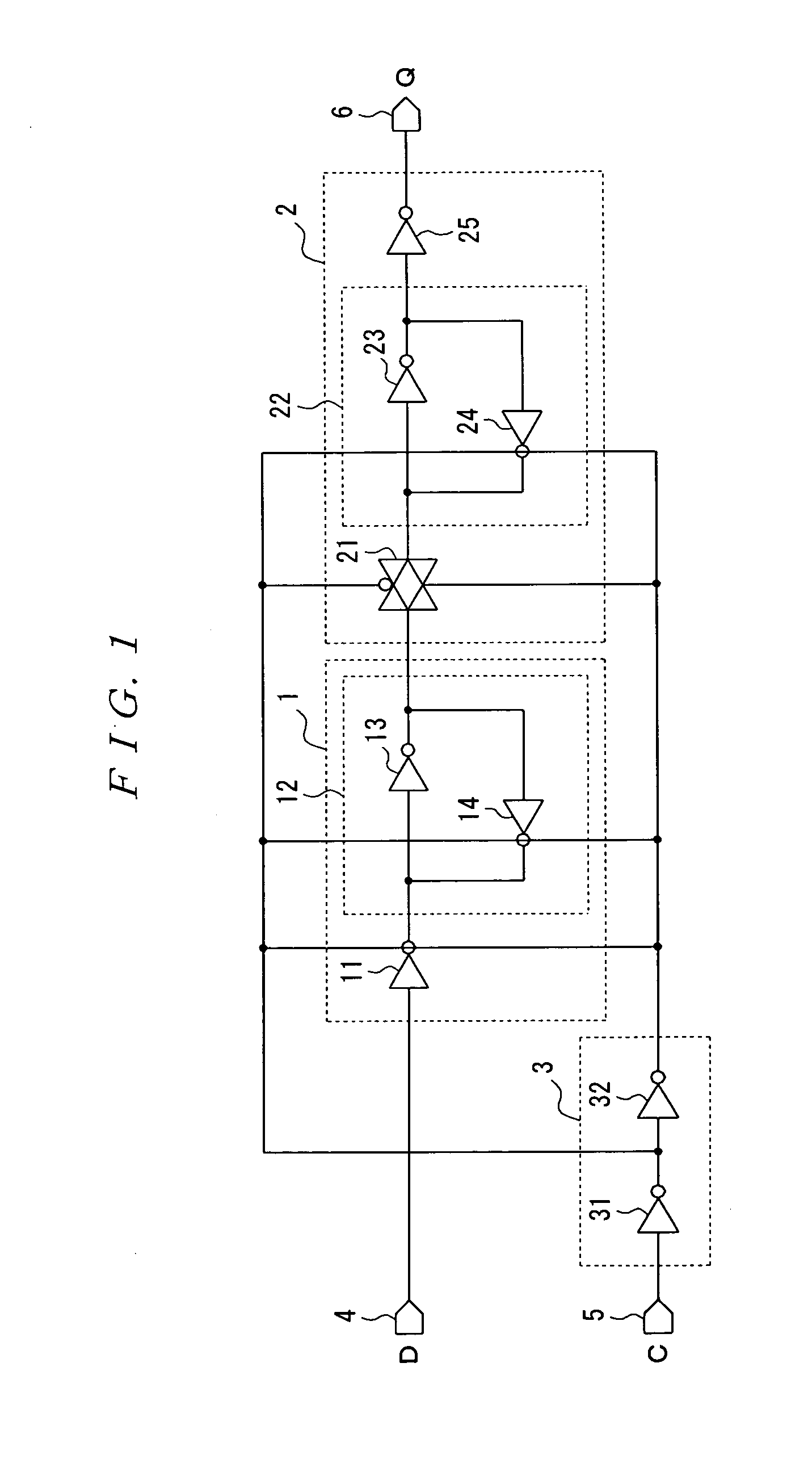
[0078]As illustrated in FIG. 1, a first embodiment related to a master-slave type flip-flop circuit of the invention comprises a master latch 1, a slave latch 2 and a clock supply circuit 3 supplying a clock thereto and is operated with a rise of the clock.

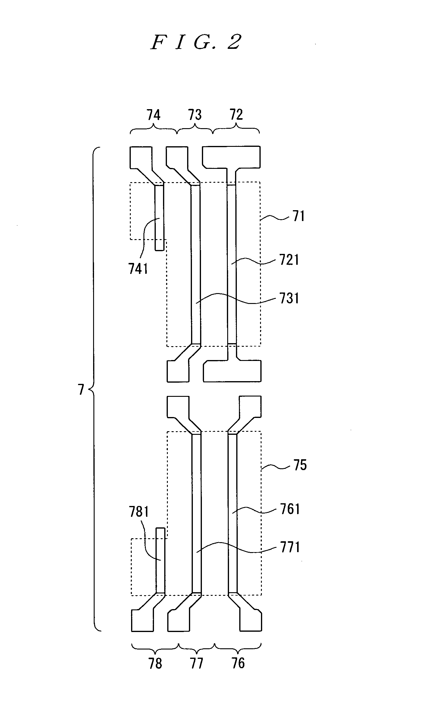
[0079]In addition, in that first embodiment, each component configuring those elements is configured with a basic cell, wherein that basic cell is made of six MOS transistors as illustrate in FIG. 2. Configuration of that basic cell will be described later.

[0080]A master latch 1 consists of a clocked inverter 11 and a latch circuit 12 in order to take in and retain data D being input to an input terminal 4. The latch circuit 12 configures a closed circuit with an inverter 13 and a clocked inverter 14 so as to be capable of retaining data.

[0081]The slave latch 2 takes in the data from the master latch 1 to retain and output those taken-in data. Therefore, the slave latch 2 consists of a transmission gate 21, a latch circuit 22 and ...

second embodiment

[0122]As illustrated in FIG. 13, a second embodiment related to a master-slave type flip-flop circuit of the invention comprises a master latch 1a, a slave latch 2a and a clock supply circuit 3 supplying a clock thereto; is operated with a rise of the clock; and has a reset (clear) function.

[0123]That is, the second embodiment is basically configured likewise the first embodiment illustrated in FIG. 1 and the master latch 1 and the slave latch 2 in FIG. 1 are replaced by the master latch 1a and the slave latch 2a.

[0124]Here, the second embodiment is basically configured likewise the first embodiment. Therefore, like reference numerals and characters designate the same components so that description thereon is omitted as much as possible.

[0125]A master latch 1a consists of a clocked inverter 11 and a latch circuit 12a so as to be capable of taking in and retaining data D being input to an input terminal 4 according to a logic of a clock C being input to a clock terminal 5 and resett...

third embodiment

[0137]As illustrated in FIG. 16, a third embodiment related to a master-slave type flip-flop circuit of the invention comprises a master latch 1b, a slave latch 2b and a clock supply circuit 3 supplying a clock thereto; is operated with a rise of the clock; and has a set function.

[0138]That is, the third embodiment is basically configured likewise the first embodiment illustrated in FIG. 1 and the master latch 1 and the slave latch 2 in FIG. 1 are replaced by the master latch 1b and the slave latch 2b.

[0139]Here, the third embodiment is basically configured likewise the first embodiment. Therefore, like reference numerals and characters designate the same components so that description thereon is omitted as much as possible.

[0140]A master latch 1b consists of a clocked inverter 11 and a latch circuit 12b so as to be capable of taking in and retaining data D being input to an input terminal 4 according to a logic of the clock C being input to a clock terminal 5 and setting a state i...


PUM


Abstract

A master-slave type flip-flop circuit consisting of a master latch and a slave latch, wherein the master latch comprises: a first clocked inverter to which data are input and a first latch circuit configuring a closed circuit with a first inverter and a second clocked inverter so that an output of the first clocked inverter is input to the first inverter and; the slave latch comprises: a transmission gate to which an output from the first latch circuit is input and a second latch circuit configuring a closed circuit with a second inverter and a third clocked inverter so that an output of the transmission gate is input to the second inverter, respective components configuring the master latch and the slave latch are configured with Sea Of Gate (hereinafter to be referred to as SOG) configuring a gate array, a basic cell of the SOG consists of triplely arrayed N-type transistors and corresponding triplely arrayed P-type transistors, the triplely arrayed N-type transistors consist of double-arrayed normally sized main transistors and one auxiliary transistor sized smaller than in a normal size and the triplely arrayed P-type transistors consist of double-arrayed normally sized main transistors and one auxiliary transistor sized smaller than in a normal size.

Description

[0001]The entire disclosure of Japanese Patent Applications No. 2007-172874 filed Jun. 29, 2007 and No. 2007-180588 filed Jul. 10, 2007, is expressly incorporated by reference herein.BACKGROUND OF THE INVENTION[0002]1. Field of the Invention[0003]The invention relates to a master-slave type flip-flop circuit consisting of a master latch and a slave latch.[0004]In addition, the invention relates to a master-slave type flip-flop circuit comprising a master latch and a slave latch and being applicable to scan design being one of test simplification designs of an integrated circuit.[0005]2. Description of the Related Art[0006]A conventional master-slave type flip-flop circuit comprises a master latch 300 and a slave latch 400 as illustrated, for example, in FIG. 33.[0007]The master latch 300 comprises an inverter 301, transmission gate 302 and a latch circuit 303. The latch circuit 303 comprises inverters 304 and 305 and transmission gate 306. The slave latch 400 comprises transmission ...

Claims


Application Information

Patent Timeline
Patent Type & Authority Applications(United States)
IPC IPC(8): H03K3/289
CPCH01L27/0207H03K3/35625H01L27/11807
Inventor KOBAYASHI, SHINICHIRO
Owner SEIKO EPSON CORP
Why Eureka
Try Eureka