
Antenna element and antenna unit capable of receiving two kinds of radio waves

a technology of antenna elements and antenna units, applied in the direction of substantially flat resonant elements, resonant antennas, instruments, etc., can solve the problem of affecting the operation of related hybrid antenna units, which is disadvantageous in that it is upsized

Inactive Publication Date: 2009-01-01
MITSUMI ELECTRIC CO LTD
View PDF5 Cites 13 Cited by
  • Summary
  • Abstract
  • Description
  • Claims
  • Application Information

AI Technical Summary

Problems solved by technology

Therefore, the related hybrid antenna unit is disadvantageous in that it is upsized.

Method used


Image

  • Antenna element and antenna unit capable of receiving two kinds of radio waves
  • Antenna element and antenna unit capable of receiving two kinds of radio waves
  • Antenna element and antenna unit capable of receiving two kinds of radio waves

Examples


Embodiment Construction

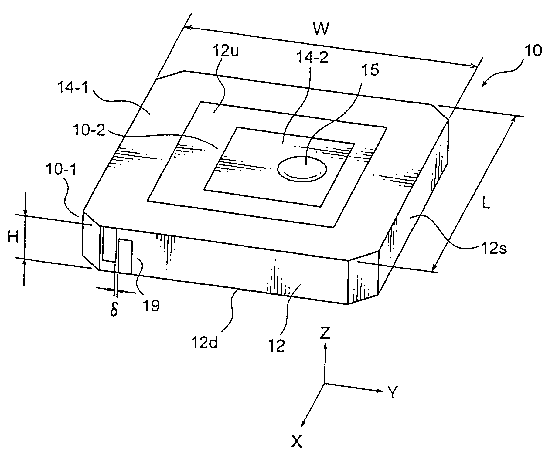
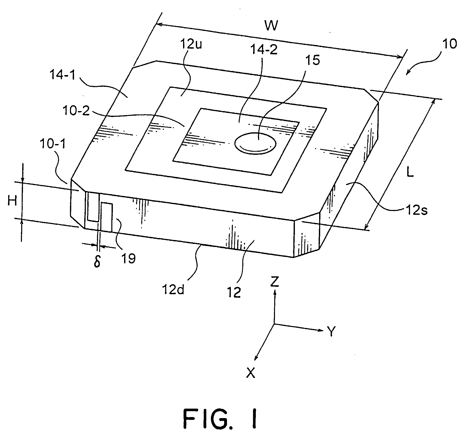
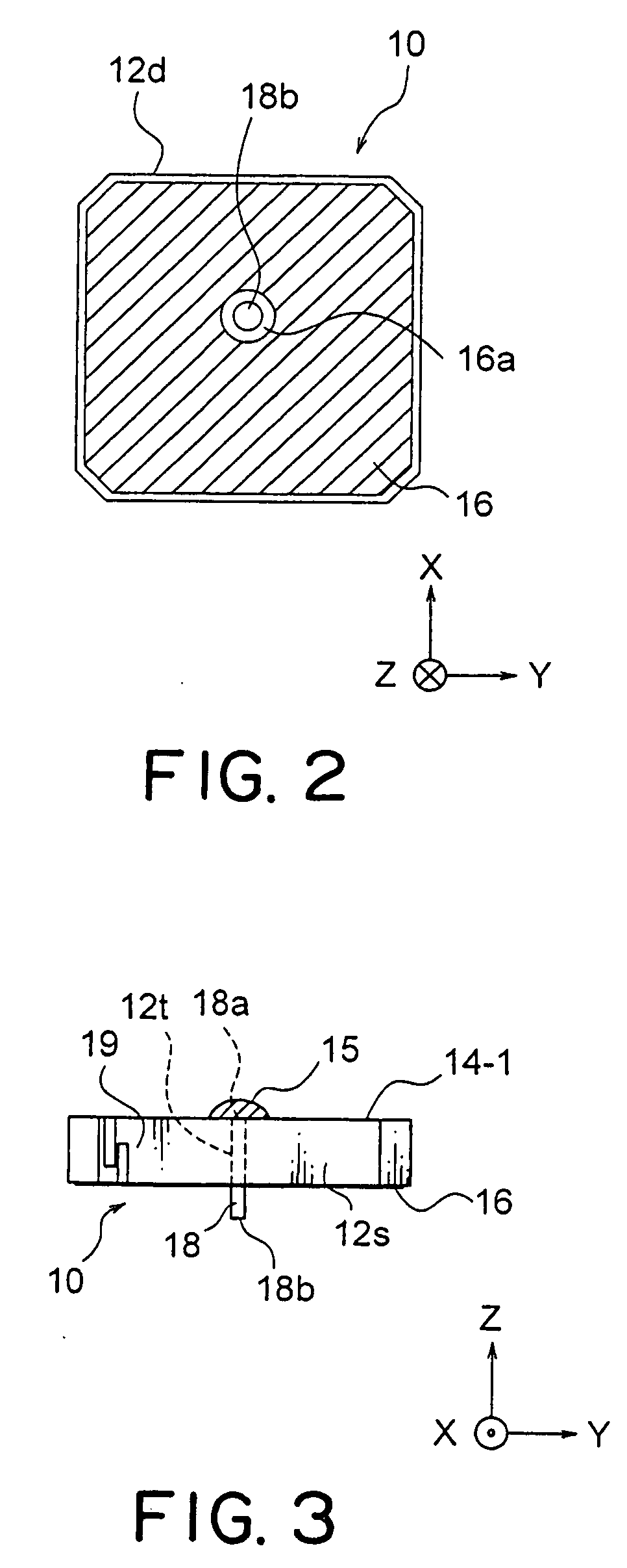
[0030]Referring to FIGS. 1 through 3, the description will proceed to an antenna element (a patch antenna) 10 according to an exemplary embodiment of the present invention. FIG. 1 is a perspective view showing the antenna element (the patch antenna) 10. FIG. 2 is a bottom view of the antenna element (the patch antenna) 10 illustrated in FIG. 1. FIG. 3 is a front view of the antenna element (the patch antenna) 10 illustrated in FIG. 1.

[0031]Herein, in the manner shown In FIGS. 1 to 3, an orthogonal coordinate system (X, Y, Z) is used. In a state illustrated in FIGS. 1 to 3, in the orthogonal coordinate system (X, Y, Z), an X-axis direction is a fore-and-aft direction (a depth direction), a Y-axis direction is a left-and-right direction (a width direction), and a Z-axis direction is an up-and-down direction (a height direction, a thickness direction).

[0032]The illustrated antenna element (the patch antenna) 10 is an antenna element for receiving first and second radio waves which are ...


PUM


Abstract

An antenna element includes a dielectric board, a first antenna radiation electrode formed on a top surface of the dielectric board at an outer region, a second antenna radiation electrode formed on the top surface of the dielectric board at a central portion, a ground electrode formed on a bottom surface of the dielectric board, a feeding pattern formed on the side surface of the dielectric board for feeding to the first antenna radiation electrode by electromagnetic coupling, and a feeding pin having an end connected to the second antenna radiation electrode. A combination of the first antenna radiation electrode, the ground electrode, and the feeding pattern serves as a first antenna portion for receiving a first radio wave. A combination of the second antenna radiation electrode, the ground electrode, and the feeding pin serves as a second antenna portion for receiving a second radio wave.

Description

[0001]This application is based upon and claims the benefit of priority from Japanese patent application No. 2007-167414, filed on Jun. 26, 2007, and Japanese patent application No. 2008-77141, filed on Mar. 25, 2008, the disclosures of which are incorporated herein their entirety by reference.BACKGROUND OF THE INVENTION[0002]This invention relates to an antenna element and an antenna unit and, in particular, to a hybrid antenna element and a hybrid antenna unit for receiving two kinds of electric waves.[0003]In the manner which is known in the art, recently, various different antennas are mounted in a vehicle such as an automobile. For example, there are, as such antennas, a GPS (Global Positioning System) antenna, an SDARS (Satellite Digital Audio Radio Service) antenna, an ETC (Electronic toll Collection) antenna, or the like.[0004]The GPS (Global Positioning System) is a satellite positioning system using artificial satellites which are called GPS satellites. The GPS is a system...

Claims


Application Information

Patent Timeline
IPC IPC(8): G01S1/00H01Q1/48G01S19/25
CPCH01Q9/0407H01Q5/40H01Q9/0464
Inventor NORO, JUNICHIIIZUKA, TAKESHIAIZAWA, TOSHIAKISATO, KYUICHI
Owner MITSUMI ELECTRIC CO LTD
Learn More