Sensor rationality diagnostic

Active Publication Date: 2009-01-01
CUMMINS EMISSION SOLUTIONS
View PDF17 Cites 29 Cited by
  • Summary
  • Abstract
  • Description
  • Claims
  • Application Information

AI Technical Summary

Benefits of technology

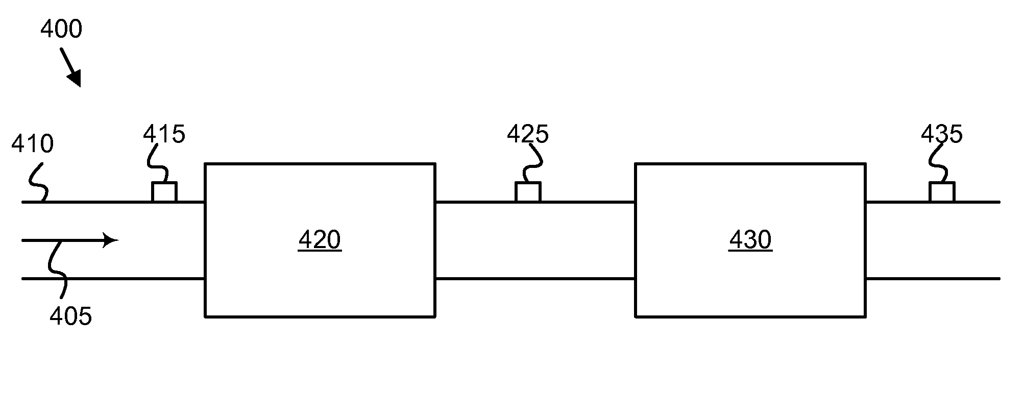
[0025]FIG. 8 is a schematic block diagram illustrating one emb

Problems solved by technology

The catalyst interacts with the exhaust as it passes through the DOC, raising the temperature of the exhaust and causing the particulate matter to burn.
In particular, in-range rationality refers to detecting temperatures within the operating range of th

Method used


Image

  • Sensor rationality diagnostic
  • Sensor rationality diagnostic
  • Sensor rationality diagnostic

Examples


Embodiment Construction

[0027]Reference throughout this specification to “one embodiment,”“an embodiment,” or similar language means that a particular feature, structure, or characteristic described in connection with the embodiment is included in at least one embodiment of the present invention. Appearances of the phrases “in one embodiment,”“in an embodiment,” and similar language throughout this specification may, but do not necessarily, all refer to the same embodiment.

[0028]The described features, structures, or characteristics of the invention may be combined in any suitable manner in one or more embodiments. In the following description, numerous specific details are supplied to provide a thorough understanding of embodiments of the invention. One skilled in the relevant art will recognize, however, that the invention may be practiced without one or more of the specific details, or with other methods, components, materials, and so forth. In other instances, well-known structures, materials, or opera...


PUM


Abstract

A sensor diagnostic method, such as to determine rationality of one of three temperature sensors used in an exhaust aftertreatment system, includes determining the temperature difference between the first and second sensor, determining the temperature difference between the second and third sensor, determining whether the temperature differences are within an acceptable threshold range and comparing the two temperature differences to determine which sensor is in error, if any.

Description

BACKGROUND OF THE INVENTION[0001]1. Field of the Invention[0002]This invention relates to sensor rationality diagnostics, more particularly, it relates to emission or exhaust control systems of internal combustion engines and apparatuses, systems, and methods for diagnosing functionality of temperature sensors associated with exhaust aftertreatment catalyst / filter systems. More specifically the invention relates to apparatuses, systems, and methods for verifying in-range thermistor rationality in exhaust aftertreatment catalyst / filter systems.[0003]2. Description of the Related Art[0004]Catalyst / filter aftertreatment systems for diesel particulate matter are designed to catch particulate matter or soot in diesel particulate filter (DPF). The DPF over time becomes filled with the particulate matter and must be cleaned. One method of cleaning a DPF is by burning off the accumulated particulate through the use of a diesel oxidation catalyst (DOC).[0005]A DOC is a flow through device co...

Claims


Application Information

Patent Timeline
IPC IPC(8): G01K15/00
CPCG01K13/00G01K15/007G01K15/00G01K2205/04G01K7/22G01K13/02G01K13/026
Inventor CORBET, TODDBERRYHILL, ROSS C.HARSHBARGER, DANIEL R.
Owner CUMMINS EMISSION SOLUTIONS
Why Eureka
Try Eureka