Correcting for carrier frequency offset in multi-carrier communication systems

a carrier frequency offset and communication system technology, applied in the field of communication systems, can solve problems such as the inability to recover data bits from multi-carrier systems accurately

Active Publication Date: 2009-01-01
TEXAS INSTR INC
View PDF8 Cites 21 Cited by
  • Summary
  • Abstract
  • Description
  • Claims
  • Application Information

AI Technical Summary

Problems solved by technology

When the offset deviates from the ideal zero, data bits from a multi-carrier system may not be recovered accurately.
Such a problem is of particular concern in telecommunication systems using Orthogonal Frequency Division Multiplexing (OFDM) techniques or Discrete Multi-tone Techniques (DMT) due to the overlap of the sub-channel frequencies, and effects of inter-channel interference (ICI) that may be caused due to carrier frequency offsets.

Method used


Image

  • Correcting for carrier frequency offset in multi-carrier communication systems
  • Correcting for carrier frequency offset in multi-carrier communication systems
  • Correcting for carrier frequency offset in multi-carrier communication systems

Examples


Embodiment Construction

Overview

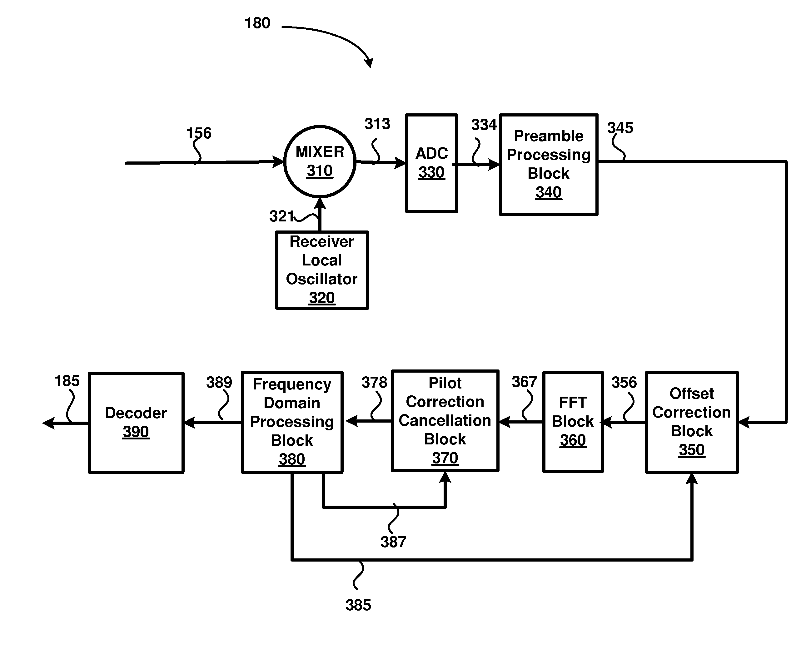
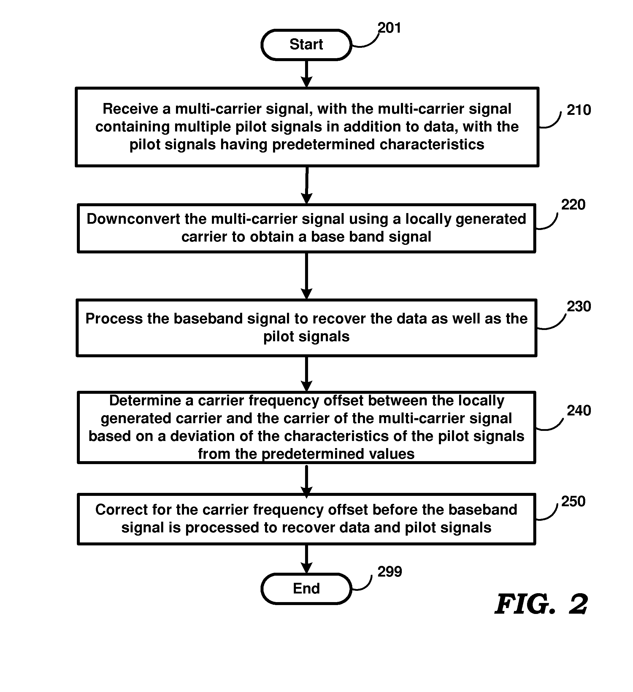
[0019]An aspect of the present invention determines a carrier frequency offset of a multi-carrier signal by examining pilot symbols in frequency domain and corrects the offset by processing the multi-carrier signal in time domain.

[0020]Due to the correction in time domain, the computational complexity may be reduced. In an embodiment, as the pilot symbols are received in parallel along with data symbols, corrections may be performed potentially for each data symbol. As a result, variations in carrier frequency offset even within a duration of a packet, may be corrected.

[0021]According to another aspect of the present invention, a multi-carrier receiver uses a phase locked loop (PLL) to track the phases of one or more pilot symbols. Changes in pilot phases caused due to carrier frequency offset correction in the time domain are cancelled to allow the PLL to operate without disruption.

[0022]According to another aspect of the present invention, a PLL used to track the phase of ...


PUM


Abstract

A multi-carrier (MC) receiver receives a multi-carrier signal containing data symbols as well as pilot symbols. The MC receiver estimates a carrier frequency offset in a downconverted base-band multi-carrier signal in the frequency domain based on deviations of one or more characteristics of the pilot signals from predetermined values, and corrects for the offset in the time domain. In an embodiment, a second order phase locked loop (PLL) estimates the phase of the pilot signals to determine the carrier frequency offset. Changes in pilot phases caused due to the time domain correction are cancelled to allow the PLL to minimize deviations from the lock position.

Description

BACKGROUND[0001]1. Field of the Invention[0002]The present disclosure relates generally to communication systems, and more specifically to a technique for correcting carrier frequency offset in multi-carrier communication systems.[0003]2. Related Art[0004]Multi-carrier communication (MC) techniques are often used both in wire-line and wireless telecommunication systems to transmit multiple streams of symbols, with each symbol typically containing one or more bits. In a MC system, a transmission band / channel is divided into a number of narrow bandwidth sub-channels, and in a transmitter device in a MC system each stream of symbols may be modulated on a corresponding sub-channel carrier signal.[0005]Generally each sub-channel carrier signal is modulated (using techniques such as Quadrature Phase Shift Keying (QPSK), Quadrature Amplitude Modulation (QAM), etc., well known in the relevant arts) to encode the corresponding stream of symbols. The resulting sub-channel signals may be added...

Claims


Application Information

Patent Timeline
Patent Type & Authority Applications(United States)
IPC IPC(8): H04L27/16
CPCH04L27/2657H04L27/2675H04L27/2672H04L27/2671
Inventor GUNTURI, SARMATANGUDU, JAWAHARLALPUVVADA, NAGASATYA SRIKANTH
Owner TEXAS INSTR INC
Why Eureka
Try Eureka