
Speaker array apparatus, microphone array apparatus, and signal processing methods therefor

a technology of array apparatus and array apparatus, applied in the direction of stereophonic arrangments, transducer casings/cabinets/supports, electrical transducers, etc., can solve the problems of enormous calculation amount and application of extremely large processing load, and achieve the effect of reducing processing load

Inactive Publication Date: 2009-01-01
YAMAHA CORP
View PDF2 Cites 19 Cited by
  • Summary
  • Abstract
  • Description
  • Claims
  • Application Information

AI Technical Summary

Benefits of technology

[0010]The present invention provides a speaker array apparatus, a microphone array apparatus, and a signal processing method, which make it possible to carry out directivity control over a wide frequency range with a reduced processing load.
[0012]The speaker array apparatus can further include a control unit adapted to change the directional characteristics of acoustic beams emitted from the plurality of sound emission devices, and the plurality of sound emission devices can include a plurality of delay devices adapted to perform delay processing on the amplified divided audio signals supplied from corresponding ones of the plurality of amplifier devices of the plurality of amplifier units, and a plurality of speakers adapted to emit sounds based on the divided audio signals subjected to the delay processing, and the control unit can control amounts of delay of the divided audio signals attained by the delay processing by the delay devices of the plurality of sound emission devices, thereby changing the directional characteristics of the acoustic beams.
[0013]The speaker array apparatus can further include a control unit adapted to change the directional characteristics of acoustic beams emitted from the plurality of sound emission devices, and each of the plurality of amplifier units of the signal processing unit can include a plurality of delay devices adapted to perform delay processing on the divided audio signals supplied from the signal divider unit to each of the plurality of amplifier units, the plurality of amplifier devices of each of the amplifier units can amplify the divided audio signals subjected to the delay processing by the plurality of delay devices of each of the amplifier units, and the control unit can control amounts of delay of the divided audio signals attained by the delay processing by the plurality of delay devices of each of the plurality of amplifier units, thereby changing the directional characteristics of the acoustic beams.
[0018]With the present invention, a speaker array apparatus, a microphone array apparatus, and a signal processing method can be provided, which make it possible to carry out directivity control over a wide frequency range with a reduced processing load.

Problems solved by technology

With the phase and amplitude control using FIR filters at individual frequency points, however, a calculation amount becomes enormous, and an extremely large processing load is applied to, for example, a DSP (digital signal processor).

Method used


Image

  • Speaker array apparatus, microphone array apparatus, and signal processing methods therefor
  • Speaker array apparatus, microphone array apparatus, and signal processing methods therefor
  • Speaker array apparatus, microphone array apparatus, and signal processing methods therefor

Examples


first embodiment

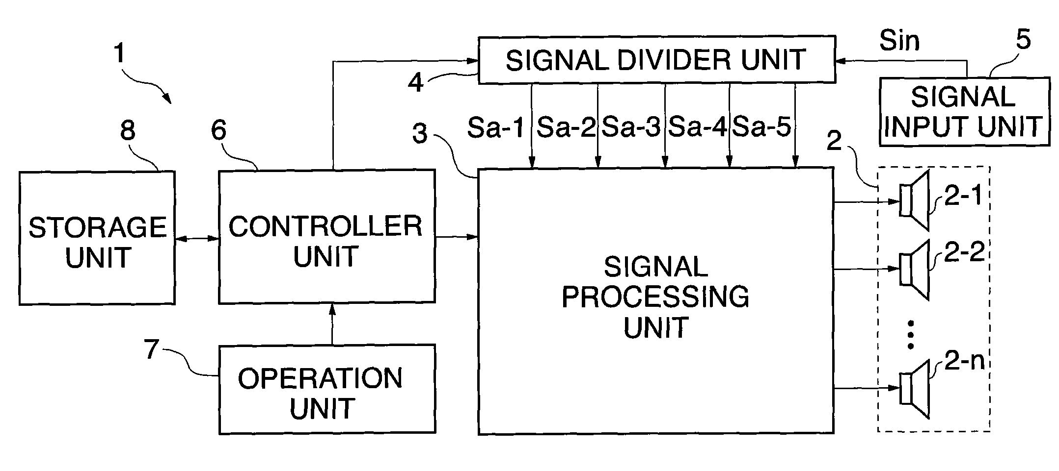
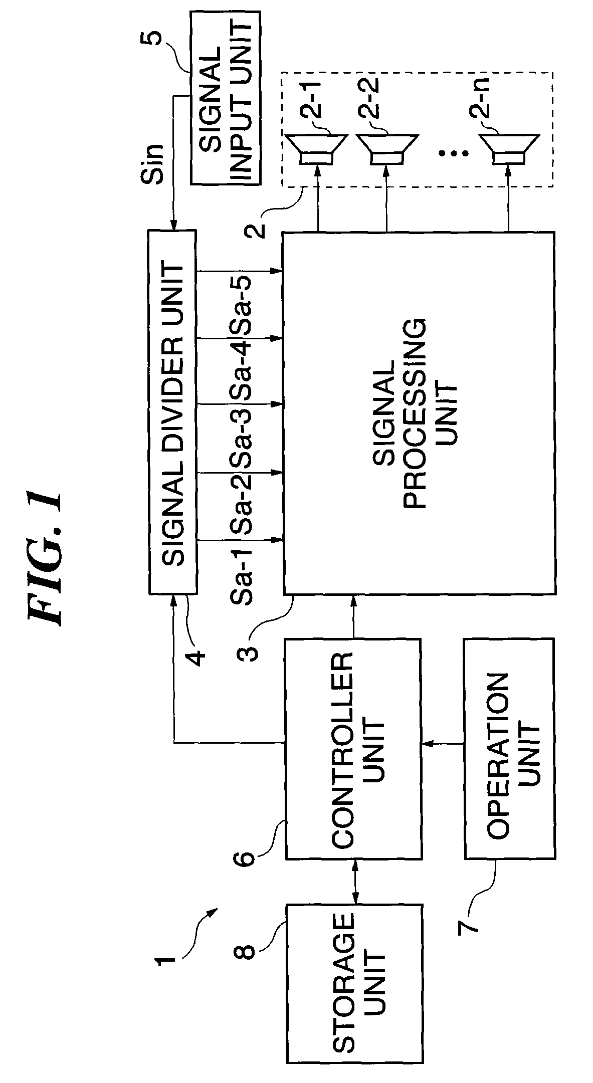
[0044]The following is a description of the construction of a speaker array apparatus 1 according to a first embodiment of this invention. FIG. 1 shows in block diagram the construction of the speaker array apparatus 1. A sound emission unit 2 of the apparatus 1 includes non-directional speakers 2-1 to 2-n disposed in line and directed to the same direction, and emits sounds based on audio signals supplied from a signal processing unit 3. Based on audio signals subjected to the below-mentioned signal processing, the speakers 2-1 to 2-n of the sound emission unit 2 emit acoustic beams of predetermined directional characteristics.

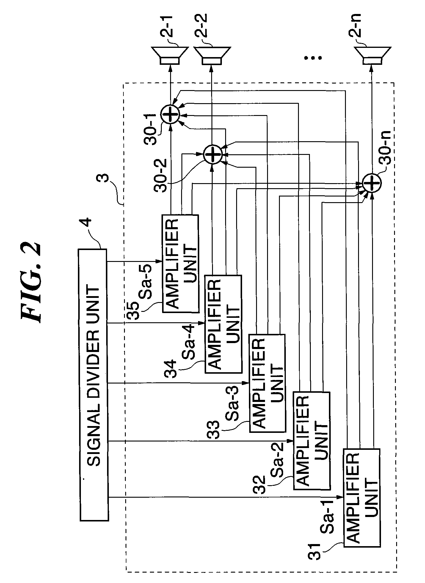
[0045]As shown in FIG. 2, the signal processing unit 3 includes amplifier units 31 to 35 and adders 30-1 to 30-n. The amplifier units 31 to 35 have the same construction. Among these, the amplifier unit 31 will be explained by way of example.

[0046]As shown in FIG. 3, the amplifier unit 31 includes amplifier circuits 31-1 to 31-n connected to the speakers 2-1 ...

second embodiment

[0089]In the first embodiment, the speaker array apparatus 1 for emitting acoustic beams having desired directional characteristics has been described. However, this invention is applicable to a microphone array apparatus comprised of directional microphones having desired directional characteristics. With reference to FIGS. 19 to 22, a microphone array apparatus 100 according to a second embodiment of this invention will be described.

[0090]As shown in FIG. 19, the microphone array apparatus 100 includes a sound pickup unit 9 having non-directional microphones 9-1 to 9-n. The sound pickup unit 9 generates a plurality of audio signals based on sounds picked up by the microphones 9-1 to 9-n, and supplies the audio signals to a signal processing unit 13. As shown in FIG. 20, the signal processing unit 13 includes amplifier units 131 to 135, which are the same in construction. As shown in FIG. 21, the amplifier unit 131 includes amplifier circuits 131-1 to 131-n and an adder 1310. In th...


PUM


Abstract

A speaker array apparatus capable of carrying out directivity control over a wide frequency range with reduced processing load. In the speaker array apparatus, an audio signal input from a signal input unit is divided into components by a signal divider unit to generate divided audio signals of different frequency ranges. The divided audio signals are amplified by amplifier units of a signal processing unit with gains set in accordance with window functions set to the amplifier units, and a sound emission unit emits sounds based on the amplified audio signals, whereby desired directional characteristics can be attained over a wide frequency range and an amount of calculation in the processing by the signal processing unit can be reduced.

Description

BACKGROUND OF THE INVENTION[0001]1. Field of the Invention[0002]The present invention relates to a speaker array apparatus and a microphone array apparatus having an improved directivity, and signal processing methods therefor.[0003]2. Description of the Related Art[0004]As a speaker system with an improved directivity, i.e., a narrow directivity, there is for example known a speaker array having a plurality of speakers mounted therein. The speaker array is adapted to control a sound directivity state by controlling the amplitude, phase, and / or other characteristics of sound to be emitted from the speakers, whereby beamed sound can be emitted toward a desired place. Since the beamed sound can be transmitted with less attenuation even to a remote place, the speaker array is often used in a large hall or the like.[0005]As a result of the directivity state control, on the other hand, the sound frequency range is likely to be narrowed. To obviate this, the following exemplary documents ...

Claims


Application Information

Patent Timeline
IPC IPC(8): H04R5/02
CPCH04R1/403H04R1/406H04R27/00H04R3/12H04R3/005
Inventor KUSHIDA, KOJI
Owner YAMAHA CORP
Learn More