Device for injection molding a tubular element from synthetic material

a tubular element and synthetic material technology, applied in the field of devices for injection molding tubular elements from synthetic materials, can solve the problems of non-uniform wall thickness of molded walls, type of molding devices, and inability to produce openings

Inactive Publication Date: 2009-01-01
VIEL +1
View PDF13 Cites 21 Cited by
  • Summary
  • Abstract
  • Description
  • Claims
  • Application Information

AI Technical Summary

Benefits of technology

[0028]The volume of material thus formed can be used to compensate for the shrinkage of the material as it

Problems solved by technology

This type of molding device has the disadvantages explained hereinbelow.
It is therefore not possible to produce an opening which is centered with respect to the tube.
The tubular element thus molded may have a wall of no

Method used


Image

  • Device for injection molding a tubular element from synthetic material
  • Device for injection molding a tubular element from synthetic material
  • Device for injection molding a tubular element from synthetic material

Examples


Embodiment Construction

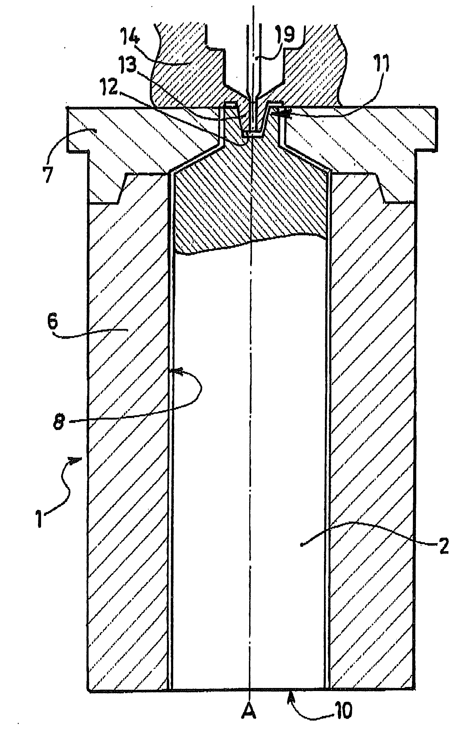
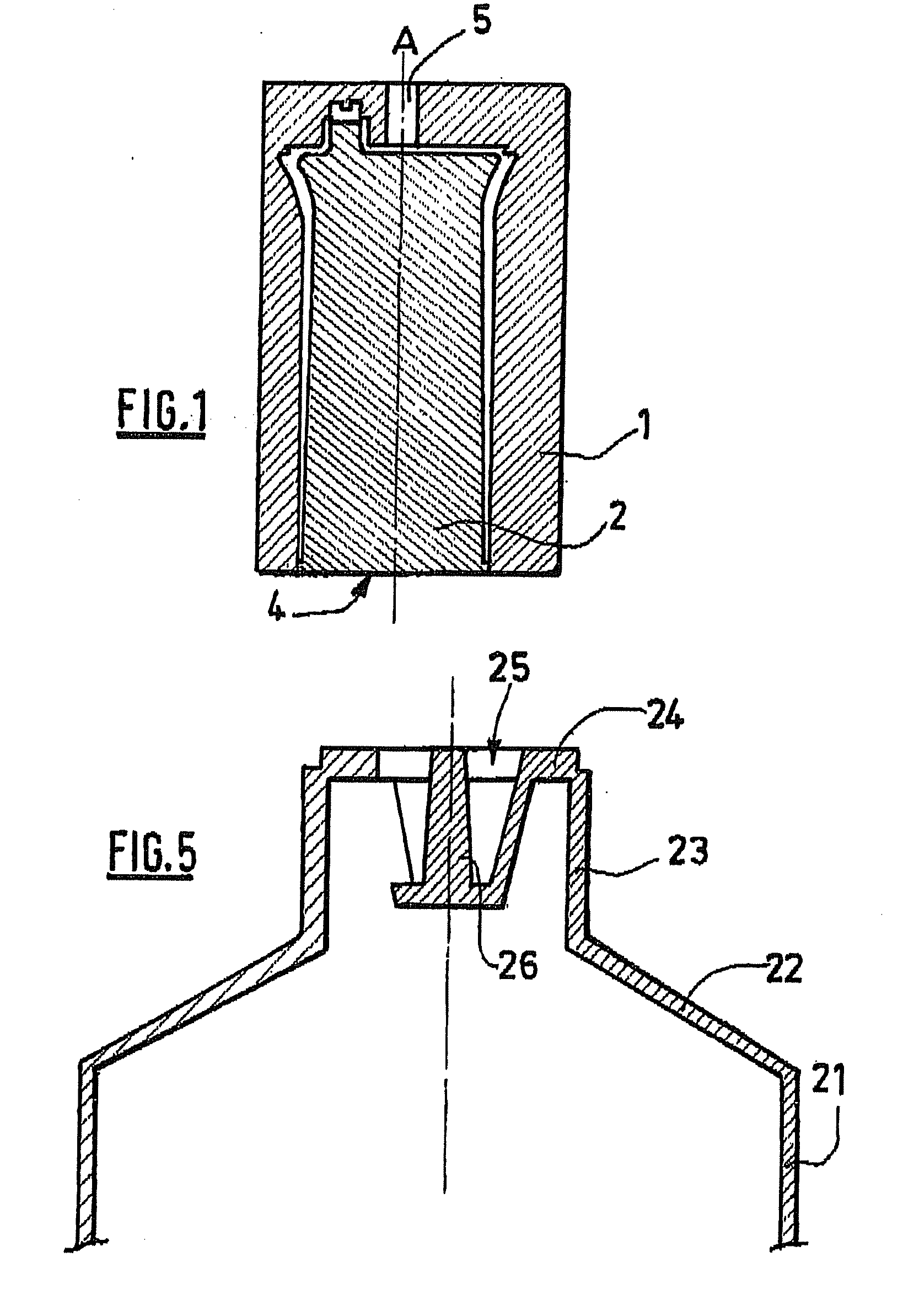
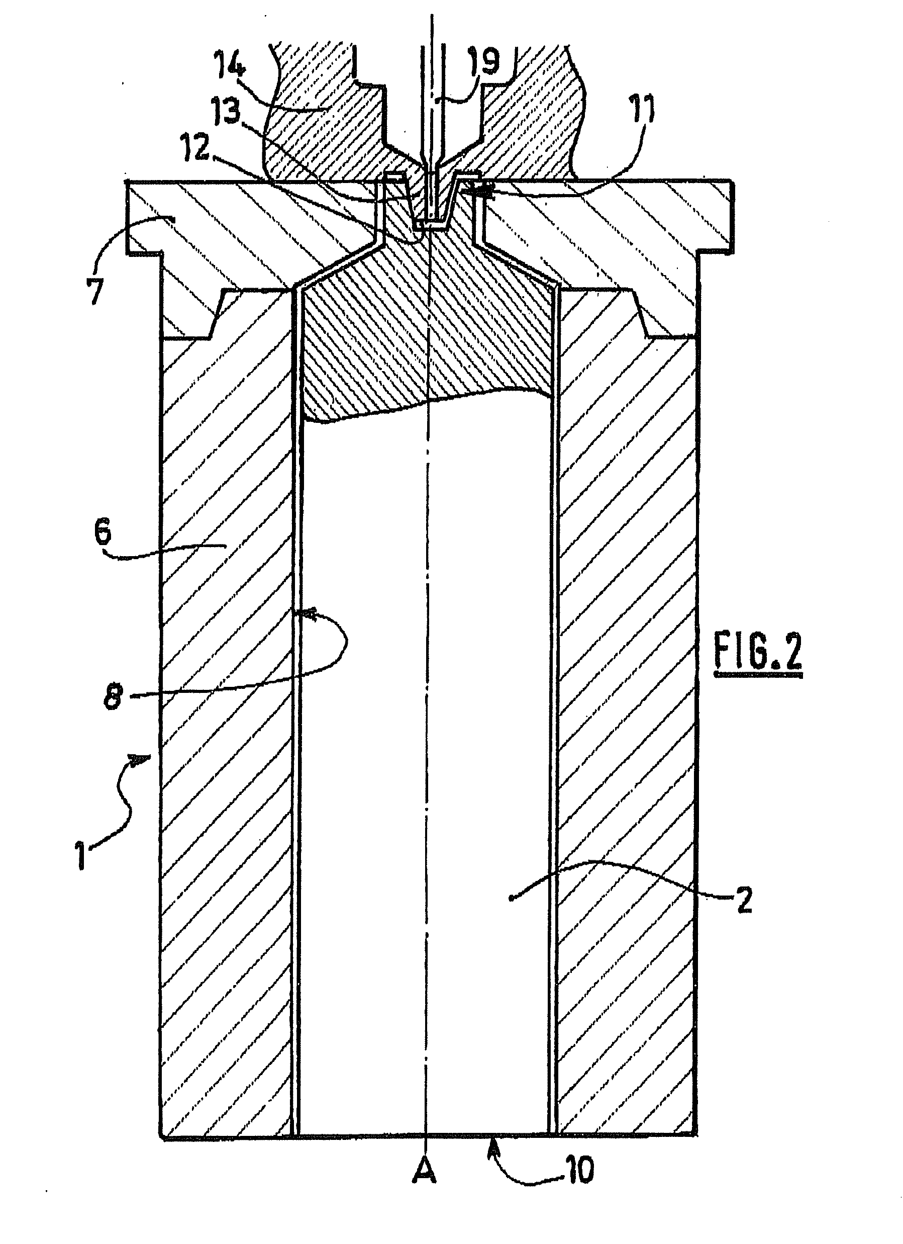
[0035]The molding device according to the invention is depicted in FIG. 2. The elements that correspond to those of the device of the prior art depicted in FIG. 1 are denoted by the same references.

[0036]The molding device according to the invention comprises an outer mold 1 formed of several parts 6, 7 assembled fixedly with respect to one another by known means.

[0037]The internal wall 8 of the outer mold 1 is intended to define the external wall of a tubular element 9. The axis of the outer mold A will be defined as being the axis of the tubular element 9 after molding.

[0038]The molding device further comprises a main insert 2 which, intended to define the internal wall of the tubular element 9, extends inside the outer mold along the axis A thereof, between a first end 10 and a second end 11.

[0039]The main insert 2 is, during the molding operation, fixedly connected to the outer mold 1 at its first end 10.

[0040]The main insert 2 may be withdrawn from the outer mold 1, during the ...


PUM

PropertyMeasurementUnit
Lengthaaaaaaaaaa
Volumeaaaaaaaaaa
Shapeaaaaaaaaaa

Abstract

The invention relates to a device for injection molding a tubular element from synthetic material, particularly a tube for dispensing pasty product, comprising an outer mold intended to define the external wall of the tubular element, a main insert which, intended to define the internal wall of the tubular element, extends along the axis of the tubular element, the main insert being fixedly connected to the outer mold at a first end during the molding operation and being movable with respect to the outer mold during a demolding operation.

Description

BACKGROUND OF THE INVENTION[0001]The invention relates to a device for injection molding a tubular element from, synthetic material, particularly a tube for dispensing pasty product.DESCRIPTION OF THE PRIOR ART[0002]A conventional molding device is known from document EP 0 040 615. As described with reference to FIG. 1, this device comprises an outer mold 1 intended to define the external wall of the tubular element.[0003]This known molding device also comprises a main insert 2 which, intended to define the internal wall of the tubular element, extends along the axis A of the tubular element, the main insert 2 being fixedly connected to the outer mold 1 at a first end 4 during a molding operation and being movable with respect to the outer mold 1 during a demolding operation.[0004]This type of molding device has the disadvantages explained hereinbelow.[0005]Synthetic material is conveyed to the outer mold via a duct 5 centered on the axis A of the tubular element. The tubular elemen...

Claims


Application Information

Patent Timeline
IPC IPC(8): B29C45/56
CPCB29C45/261B29C45/2701B29L2023/20B29C2045/363B29C45/36
Inventor VIEL, DANIELLAFOURCADE, JEAN-YVES
Owner VIEL
Why Eureka
Try Eureka