Fuel Cell
- Summary
- Abstract
- Description
- Claims
- Application Information
AI Technical Summary
Benefits of technology
Problems solved by technology
Method used
Image

Examples
first embodiment
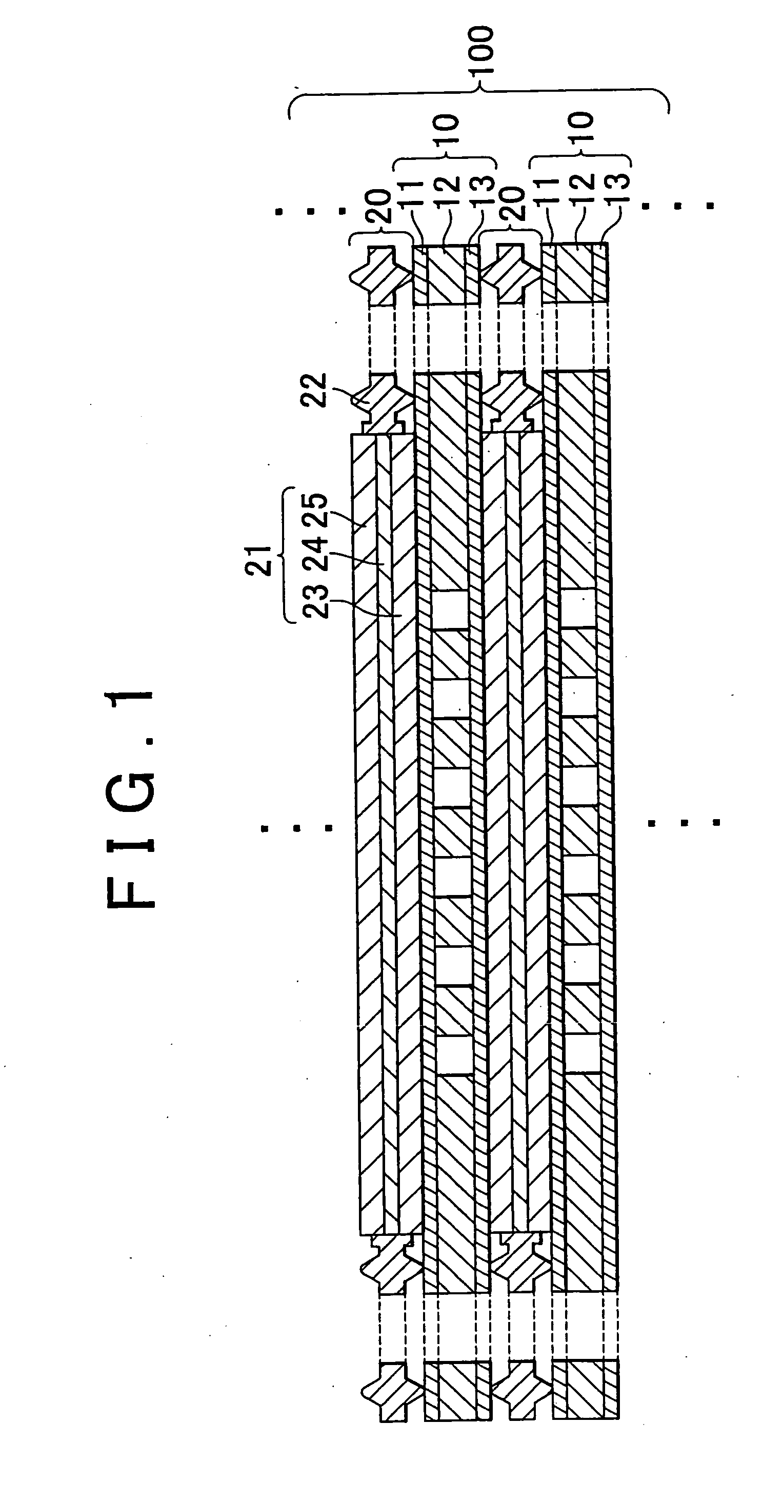
[0041]FIG. 1 is the view schematically showing a fuel cell 100 according to the invention. As shown in FIG. 1, the fuel cell 100 has a structure where separators 10 and sealing gasket-combined MEAs 20 are alternately stacked on top of each other. Each separator 10 has a structure where an intermediate plate 12 is sandwiched between a cathode-facing plate 11 and an anode-facing plate 13. These three plates 11, 12, and 13 forming the separator 10 are fitted to each other by, for example, hot pressing.
[0042]Each sealing gasket-combined MEA 20 includes an MEA (membrane electrode assembly) 21 and a sealing gasket portion 22. The MEA 21 includes an electric-power generation portion 24 in which catalytic layers are formed on respective faces of an electrolyte membrane having proton conductivity; a gas diffusion layer 23 formed on the bottom face of the electric-power generation portion 24; and a gas diffusion layer 25 formed on the top face of the electric-power generation portion 24. In t...
second embodiment
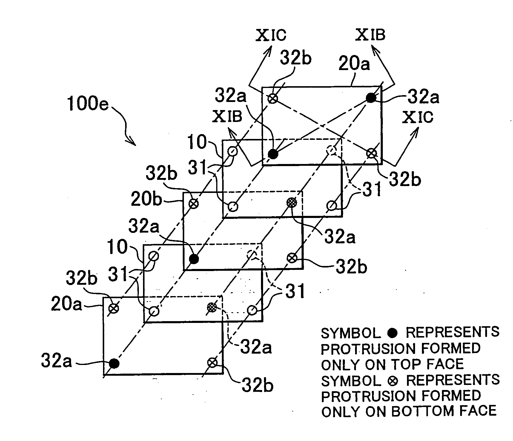
[0064]FIGS. 7A and 7B are the views used to describe a fuel cell 100a according to the invention. The fuel cell 100a differs from the fuel cell 100 in FIG. 1 in that the protrusions 32 are formed on both faces of only one corner portion of each sealing gasket-combined MEA 20. The fuel cell 100a will be described below in detail. FIG. 7A is the exploded perspective view schematically showing the fuel cell 100a. FIG. 7B is the cross-sectional view taken along the line VIIB-VIIB in FIG. 7A.
[0065]As shown in FIG. 7A, in each sealing gasket-combined MEA 20a, the protrusions 32a are formed on both faces of one of the four corner portions. In each sealing gasket-combined MEA 20b, the protrusions 32b are formed on both faces of the corner portion diagonally opposed to the corner portion of the sealing gasket-combined MEA 20a, at which the protrusion 32a is formed. In each separator 10, the through-holes 31 are formed in the corner portions corresponding to the protrusions 32a and 32b. In th...
third embodiment
[0066]FIG. 8 is the exploded perspective view schematically showing a fuel cell 100b according to the invention. The fuel cell 100b differs from the fuel cell 100 in FIG. 1 in that the protrusions 32 are formed on both faces of three portions of each sealing gasket-combined MEA 20. The fuel cell 100b will be described below in detail.
[0067]As shown in FIG. 8, in each sealing gasket-combined MEA 20a, the protrusions 32a are formed on both faces of each of the two corner portions at one end and both faces of the center portion of the side portion at the other end. In each sealing gasket-combined MEA 20b, the protrusions 32b are formed on both faces of the two corner portions at the other end and both faces of the center portion of the side portion at the one end. In each separator 10, the through-holes 31 are formed at the respective corner portions and the center portions of the side portions corresponding to the protrusions 32a and 32b. In this case, it is possible to appropriately ...
PUM
 Abstract
Description
Claims
Application Information
 - R&D Engineer
- R&D Manager
- IP Professional
- Industry Leading Data Capabilities
- Powerful AI technology
- Patent DNA Extraction
Browse by: Latest US Patents, China's latest patents, Technical Efficacy Thesaurus, Application Domain, Technology Topic.
© 2024 PatSnap. All rights reserved.Legal|Privacy policy|Modern Slavery Act Transparency Statement|Sitemap