Method for producing shallow trench isolation

Inactive Publication Date: 2009-01-01
EON SILICON SOLUTION
View PDF11 Cites 1 Cited by
  • Summary
  • Abstract
  • Description
  • Claims
  • Application Information

AI Technical Summary

Benefits of technology

[0012]when a plurality of second grooves are formed on the periphery of the first grooves via the oxidation process, the edges of the first polysilicon layer, the silicon layer and the oxide layer which are not etched in the Step (1) will be oxidized. Moreover, because the first polysilicon layer is more easily to be oxidized than the silicon layer and the oxide layer, the insulating layer formed on the first

Problems solved by technology

The conventional technique of preventing the oxide layer from thinning employed the corner rounding tech

Method used


Image

  • Method for producing shallow trench isolation
  • Method for producing shallow trench isolation
  • Method for producing shallow trench isolation

Examples


Embodiment Construction

[0016]The present invention will be described in details with the following embodiments in conjunction with the attached figures for fully understanding the objects, features and effects of the present invention. The description is as follows:

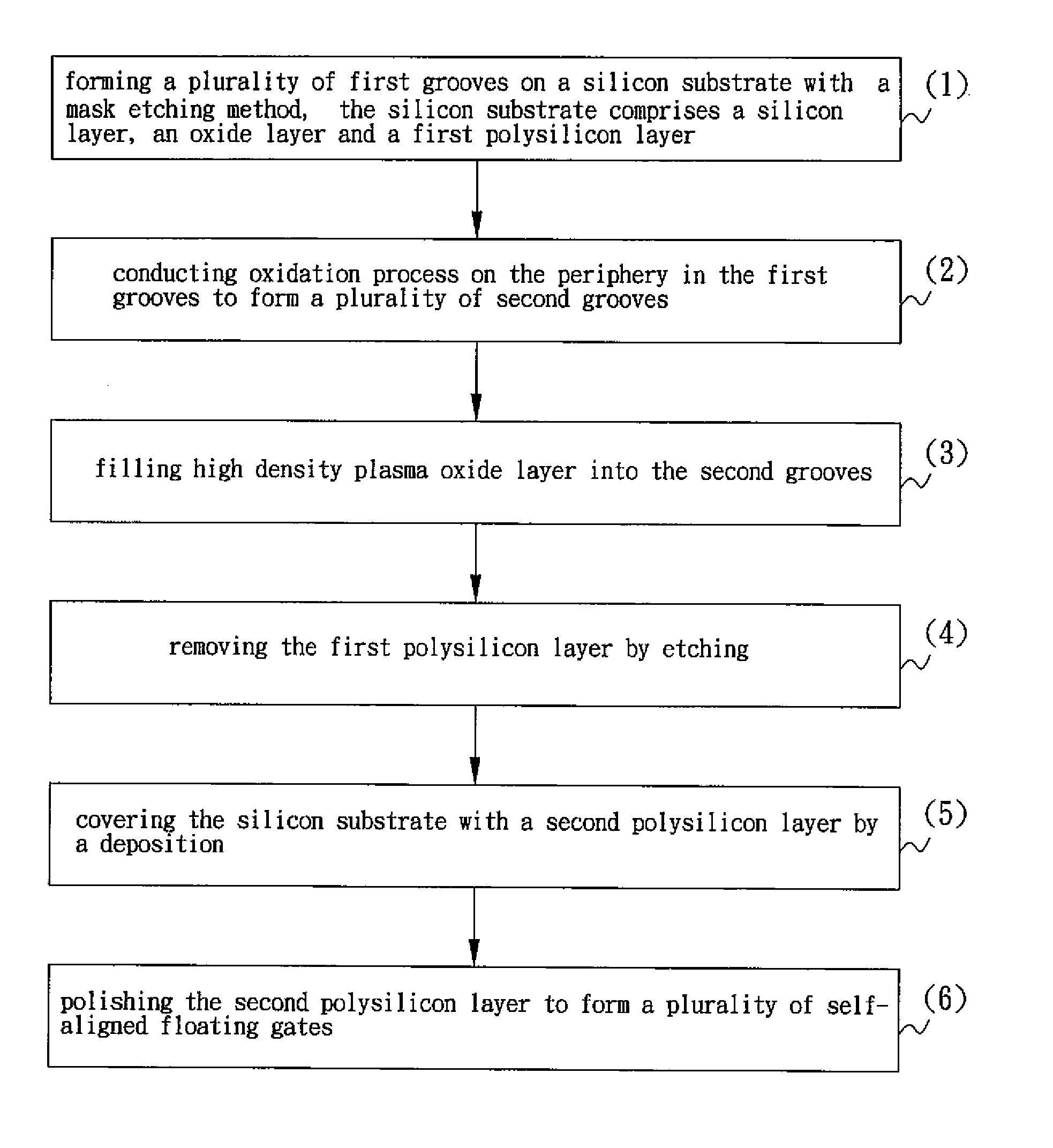
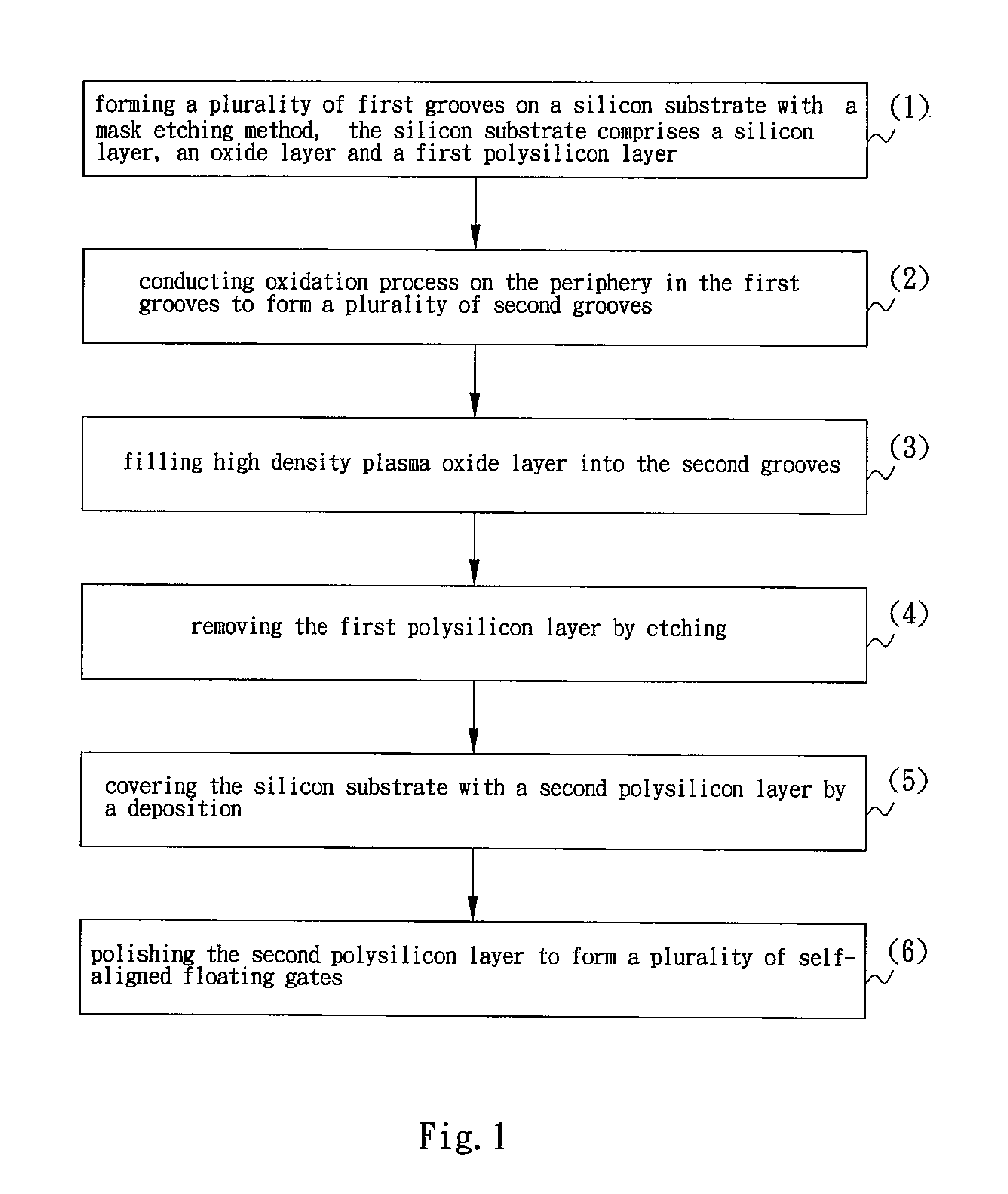
[0017]FIG. 1 is a flow chart of a method for producing shallow trench isolation according to a preferred example of the present invention. Please refer to FIG. 1, the shallow trench isolation method of the present invention comprises:

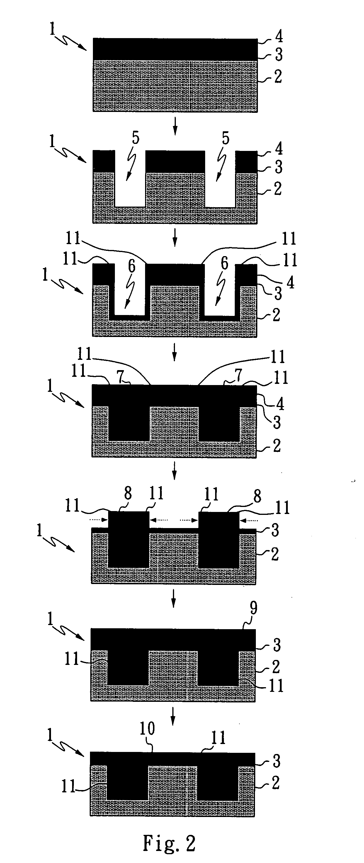
[0018](1) forming a plurality of first grooves on a silicon substrate with a mask etching method, in which those first grooves are also called the shallow trench grooves, wherein the silicon substrate comprises a silicon layer (such as a silicon nitride layer, but not limited to), an oxide layer and a first polysilicon layer (such as a buffer polysilicon layer, but it does not limited to);

[0019](2) conducting oxidation process on the periphery in the first grooves (such as the dry / wet oxidation process for the furn...


PUM


Abstract

The present invention provides a method for producing a shallow trench isolation, comprises: forming a plurality of first grooves on a silicon substrate with a mask etching method, wherein the silicon substrate comprises a silicon layer, an oxide layer and a first polysilicon layer; conducting oxidation process on an inner peripheral portion of the second grooves to form an insulting layer. The depth of the insulating layer on the periphery of the first polysilicon layer formed by the oxidation process is larger than the depths of the insulating layers that are formed on the silicon layer and on the oxidation layer through the oxidation process; filling high density plasma oxide layer into the second grooves to form a plurality of high density plasma oxide layer fillers; removing the first polysilicon layer by etching; covering the silicon substrate with a second polysilicon layer by deposition; and polishing the second polysilicon layer to form a plurality of self-aligned floating gate.

Description

TECHNICAL FIELD[0001]The present invention provides a method for producing shallow trench isolation, and particularly to a method for producing shallow trench isolation preventing from over etching of self-aligned floating gate.BACKGROUND OF THE INVENTION[0002]The shallow trench isolation (STI) technology has been developed as a necessary technical solution in the deep sub-micron semiconductor processing. As a result, the edge process of STI has become e one of the important topics, it must be able to eliminate the corner effect of the device, and maintain a complete gate oxide layer. Due to the decrease of thickness for the oxide layer, the above-mentioned topic becomes more important. Especially, the thinning effect of the oxide layer should be minimized in order to control the device. The conventional technique of preventing the oxide layer from thinning employed the corner rounding technique, but it still could not fully resolve the thinning problem of the oxide layer caused by ...

Claims


Application Information

Patent Timeline
IPC IPC(8): H01L21/461
CPCH01L21/76224H01L21/76205
Inventor LEE, YUNG CHUNG
Owner EON SILICON SOLUTION
Why Eureka
Try Eureka