Controller for a Solenoid Operated Valve

a solenoid operated valve and control box technology, applied in the direction of electrical control, process and machine control, etc., can solve the problems of inability to detect this small current change, difficulty in reliably measuring the small change, and affecting the performance of the engine, so as to improve the performance of the solenoid operated valve and fast acting solenoids

Active Publication Date: 2009-01-01
WOODWARD GOVERNOR CO
View PDF14 Cites 17 Cited by
  • Summary
  • Abstract
  • Description
  • Claims
  • Application Information

AI Technical Summary

Benefits of technology

[0010]It is an aim of the present invention to alleviate the aforementioned problems and in particular to provide for accurate timing measurements in order to improve solenoid operated valve performance in, for example: fuel injection systems including diesel fuel common rail injector systems; diesel unit injectors; petrol injection solenoids; solenoids of the two-position type; particularly fast acting solenoids; solenoids for precise dosing of fluids; pilot valves for larger actuators; engine air intake and exhaust valves (if actuated, not cam driven); valves used in suspension or braking.

Problems solved by technology

The performance of the engine (balance between cylinders, power, fuel consumption, emissions) is thus affected.
This is very hard because of the small size of the change.
Often detecting this small current change is not possible because there is no current flowing at this time, and thus no change can be measured.
Again there is difficulty in reliably measuring the small changes.
However, adding additional transducers considerably increases the system cost, and also increases complexity.
Changes in the operating conditions or parameters of the valves within a fuel injection system, for example wear, can lead to changes in the time of the valve return stroke.

Method used


Image

  • Controller for a Solenoid Operated Valve
  • Controller for a Solenoid Operated Valve
  • Controller for a Solenoid Operated Valve

Examples


Embodiment Construction

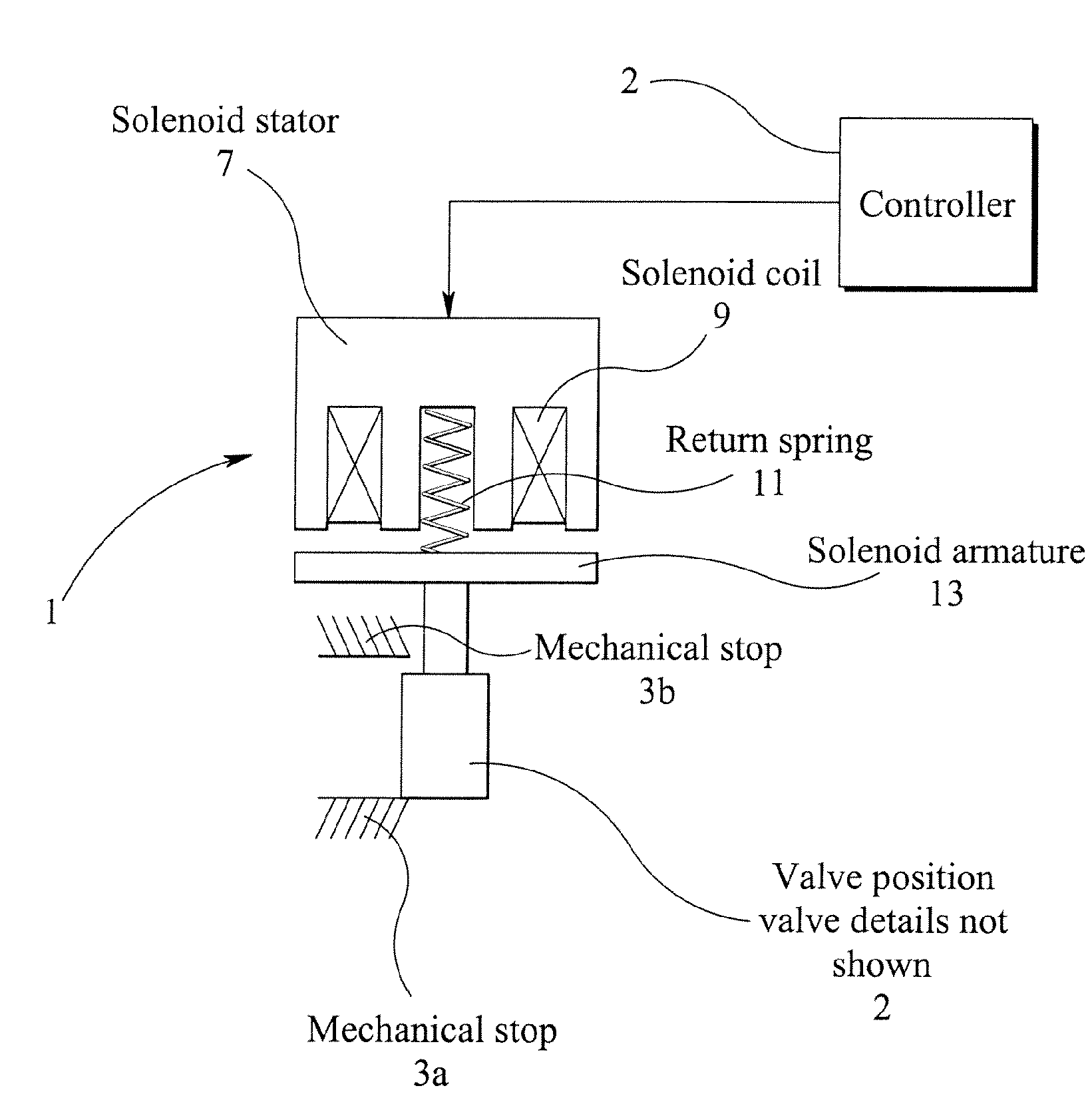
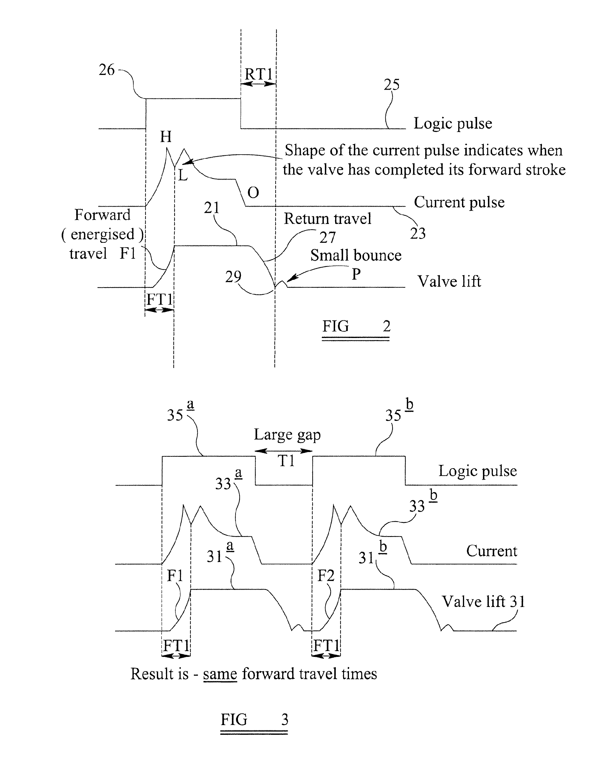
[0032]In FIG. 1, a solenoid valve shown generally by numeral 1 comprises a valve 2 is moveable between mechanical stops 3a and 3b. The valve 2 is driven by a solenoid having a stator 7, solenoid coil 9, return spring 11, and armature 13. This operates in accordance with conventional solenoid valves, namely, that when a current is applied to the solenoid valve 1 from a governor controller 4, the armature 13 is pulled from its stable state towards the stator 7 thus bringing the valve 2 to the mechanical stop or seat 3b. When the current is switched off, the return spring 11 pushes the armature 13 and hence the valve 2 back to the stop 3a. On impacting the stop 3a, it can bounce up to 10 or 20% (example percentage only) of the return travel distance. Experimental evidence shows that there may be a second and possibly a third bounce as is explained below with reference to FIG. 6. In embodiments of the invention, the valve may be of various types, for example, may have a single seat that...


PUM


Abstract

A controller moves a solenoid operated valve with a first solenoid operating pulse during a travel time. After a time interval, the controller applies a second pulse, which moves the valve towards its original position. The time interval may be varied, and a characteristic indicative of the return of the valve to the original position may be detected based on a comparison of the pulses.

Description

RELATED APPLICATIONS[0001]This application claims priority to, and the benefit of, United Kingdom patent application Serial No. GB0712538.8, filed on Jun. 28, 2007, entitled “Controller for a Solenoid Operated Valve.”FIELD OF THE INVENTION[0002]This invention relates to a controller for a solenoid operated valve and in particular but not exclusively, solenoid operated fuel injector valves, and valves used in diesel fuel injectors.BACKGROUND OF THE INVENTION[0003]The solenoid is often combined with a two-position valve, whereby the valve is pulled by the solenoid (when energized) and returned by a spring (when de-energized). The valve attached to the solenoid can be closed in one position and open in the second position, or it can be a changeover valve with two seats. In some applications, such as fuel injectors, it is desirable to measure and control the timing of the opening and closing positions of the solenoid operated valves.[0004]Diesel fuel injectors need to have precise opera...

Claims


Application Information

Patent Timeline
Patent Type & Authority Applications(United States)
IPC IPC(8): F02D41/30
CPCF02D41/20F02D41/2432F02D2041/2055F02D41/247F02D41/2438H01F7/18F02D41/02F02M61/16F02M63/00
Inventor ASKEW, JAMES M. ANDERTON
Owner WOODWARD GOVERNOR CO
Why Eureka
Try Eureka