Pneumatic Tire

a technology of pneumatic tires and springs, applied in the field of pneumatic tires, can solve the problems of increasing the constant of the vertical spring, reducing the steering stability in the low and middle speed range, and reducing the riding comfort, so as to increase the ground contact area, increase the steering stability, and increase the riding comfort

Inactive Publication Date: 2009-01-08
BRIDGESTONE CORP
View PDF7 Cites 4 Cited by
  • Summary
  • Abstract
  • Description
  • Claims
  • Application Information

AI Technical Summary

Benefits of technology

[0006]In such a pneumatic tire, the metal cords inclined at a small inclination angle with respect to the tire equator are embedded in the belt layer, and the reinforcement cords extending substantially in parallel with the tire equator are embedded in the belt reinforcement layer. Thus, when an internal pressure is charged into the pneumatic tire, high tension occurs in the metal cords in the belt layer and the reinforcement cords in the belt reinforcement layer, thereby increasing circumferential bending rigidity of the belt layer and the belt reinforcement layer, that is, a composite value of the circumferential bending rigidity.
[0007]This restricts the circumferential out-of-plane bending deformation in the ground contact as described above, thereby increasing a vertical spring constant to reduce riding comfort, reducing a ground contact length to reduce a ground contact area, and reducing steering stability in low and middle speed ranges.
[0008]The present invention has an object to provide a pneumatic tire capable of increasing both riding comfort and steering stability while maintaining high speed durability of the tire.

Problems solved by technology

This restricts the circumferential out-of-plane bending deformation in the ground contact as described above, thereby increasing a vertical spring constant to reduce riding comfort, reducing a ground contact length to reduce a ground contact area, and reducing steering stability in low and middle speed ranges.

Method used


Image

  • Pneumatic Tire
  • Pneumatic Tire
  • Pneumatic Tire

Examples


example 1

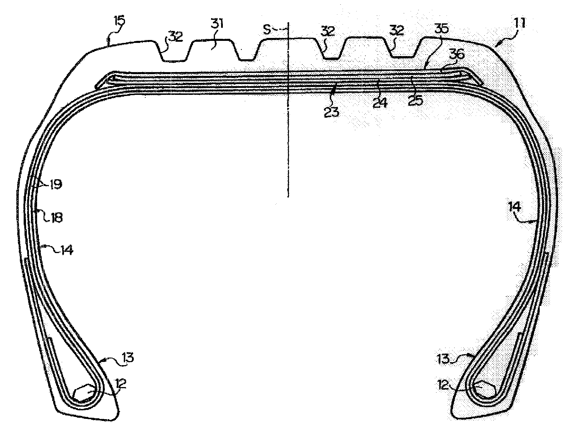
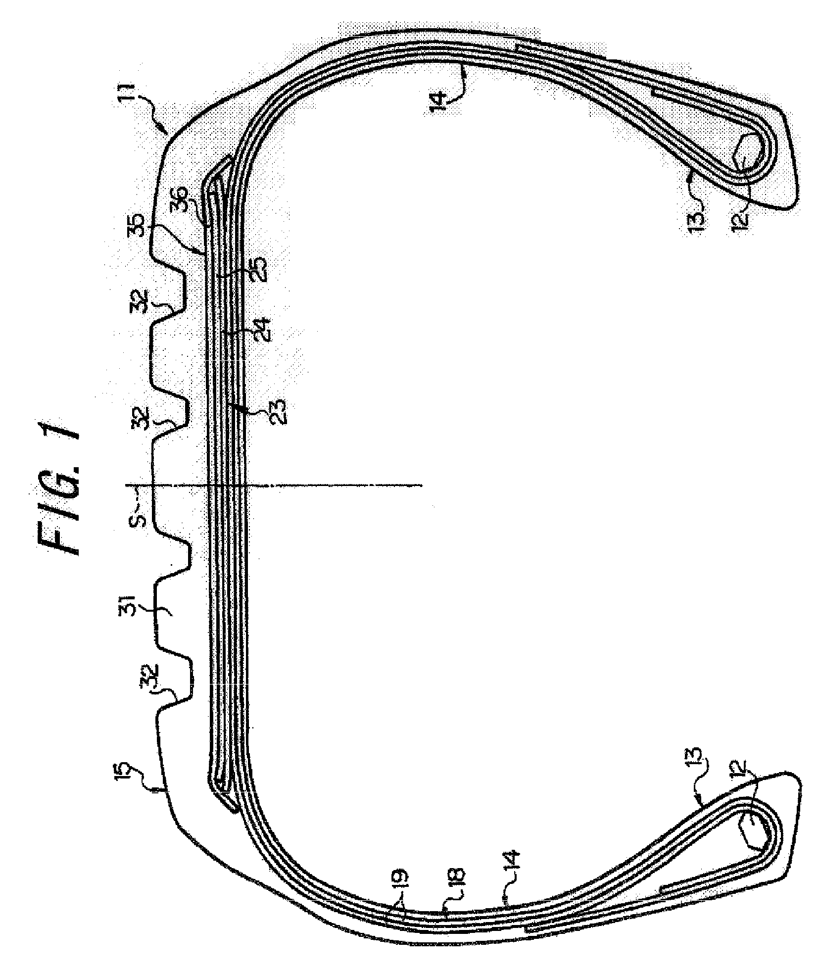
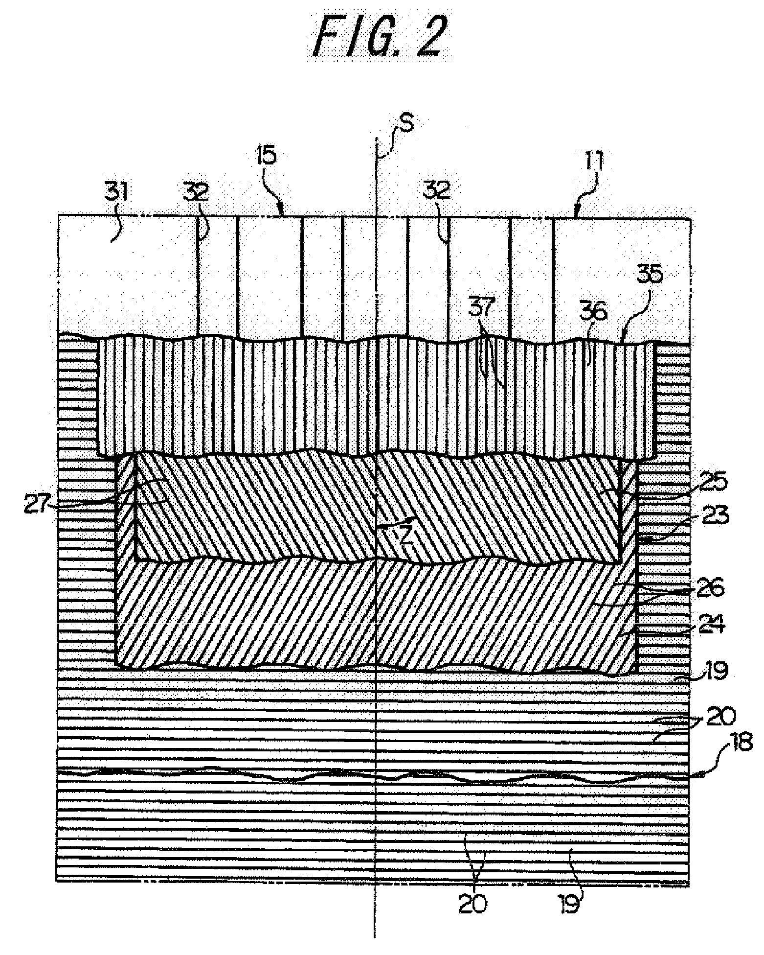
[0088]Next, Test Example 1 will be described. In this test, there were prepared: a conventional tire 1 as shown in FIGS. 1 and 2 in which cords A are embedded in remote and contact belt plies at a placement interval (a distance between center points of adjacent belt cords) of 1.2 mm; a conventional tire 2 similar to the conventional tire 1 except that belt cords in the remote and contact belt plies are cords B; an embodiment tire 1 as shown in FIGS. 1 and 2 in which the cords B are embedded in the remote belt ply at a placement interval of 1.2 mm and the cords A are embedded in the contact belt ply at a placement interval of 1.2 mm; an embodiment tire 2 similar to the embodiment tire 1 except that belt cords in the remote belt ply are cords C; an embodiment tire 3 similar to the embodiment tire 1 except that belt cords in the remote belt ply are cords D and belt cords in the contact belt ply are cords E; and an embodiment tire 4 similar to the conventional tire 1 except that placeme...

example 2

[0096]Next, Test Example 2 will be described. In this test, there were prepared: a conventional tire 3 as shown in FIGS. 3 and 4 in which cords A are embedded in remote, intermediate, and contact belt plies at a placement interval of 1.2 mm; a conventional tire 4 similar to the conventional tire 3 except that belt cords in the remote, intermediate, contact belt plies are cords B; an embodiment tire 5 similar to the conventional tire 3 except that belt cords in the remote and intermediate belt plies are the cords B; and a comparative tire 5 similar to the embodiment tire 5 except that the cords in the remote belt ply and the cords in the contact belt ply are interchanged.

[0097]Each of the tires was a high performance tire for a passenger car having the size of 245 / 55R17, a carcass layer of each tire was constituted by two carcass plies in which nylon cords that cross the tire equator S at 90 degrees are embedded, and reinforcement cords constituted by strands of aromatic polyamide fi...

example 3

[0101]Next, Test Example 3 will be described. In this test, there were provided: a conventional tire 5 as shown in FIG. 5 in which inclination angles θ of belt cords in a next adjacent belt ply and an adjacent belt ply are 40 degrees to the upper right and 40 degrees to the upper left, respectively, and an inclination angle of a reinforcement cord in a belt reinforcement layer is 0 degree; an embodiment tire 6 similar to the conventional tire 5 except that the inclination angles θ of the belt cords in the next adjacent belt ply and the adjacent belt ply are 60 degrees to the upper right and 20 degrees to the upper left, respectively; and a comparative tire 6 similar to the conventional tire 5 except that the inclination angles θ of the belt cords in the next adjacent belt ply and the adjacent belt ply are 20 degrees to the upper right and 60 degrees to the upper left, respectively.

[0102]Each of the tires was a high performance tire for a passenger car having the size of 245 / 55R17, a...


PUM


Abstract

There is provided a pneumatic tire in which a belt reinforcement layer is placed and capable of increasing both riding comfort and steering stability. Circumferential bending rigidity of a contact belt ply 25 placed in contact with the belt reinforcement layer 35 is made higher than circumferential bending rigidity of a remote belt ply 24, and thus the belt reinforcement layer 35 having high circumferential bending rigidity and the contact belt ply 25 having next high circumferential bending rigidity are collected near a neutral axis of bending positioned near a boundary thereof. Thus, composite circumferential bending rigidity of the belt layer 23 and the belt reinforcement layer 35 is reduced to reduce a vertical spring constant of the pneumatic tire 11 and increase a ground contact length.

Description

TECHNICAL FIELD[0001]The present invention relates to a pneumatic tire in which a belt reinforcement layer overlying a belt layer is placed in a tread portion.RELATED ART[0002]A known conventional pneumatic tire of this type is as described in, for example, Patent Document 1.[0003]This pneumatic tire includes a carcass layer having opposite ends in a width direction folded around bead cores and toroidally extending, a belt layer placed radially outward of the carcass layer and constituted by two belt plies in which metal cords inclined in opposite directions at the same angle within the range of 15 to 35 degrees with respect to the tire equator are embedded, a tread placed radially outward of the belt layer, and a belt reinforcement layer placed between the belt layer and the tread and in which reinforcement cords made of organic fiber and extending substantially in parallel with the tire equator are embedded.[0004]In the pneumatic tire, the reinforcement cords extending substantial...

Claims


Application Information

Patent Timeline
Patent Type & Authority Applications(United States)
IPC IPC(8): B60C9/18
CPCB60C9/2009Y10T152/10765Y10T152/10783B60C9/22
Inventor KAWAI, TAKASHIKOIDE, MASAFUMIISHIYAMA, MAKOTO
Owner BRIDGESTONE CORP
Why Eureka
Try Eureka