
Pneumatic Tire

a pneumatic tire and tire technology, applied in the field of pneumatic tires, can solve the problems of reducing rolling resistance and likely degrading rolling resistance, and achieve the effect of improving braking performance on ice and reducing rolling resistan

Pending Publication Date: 2021-03-18
YOKOHAMA RUBBER CO LTD
View PDF10 Cites 0 Cited by
  • Summary
  • Abstract
  • Description
  • Claims
  • Application Information

AI Technical Summary

Benefits of technology

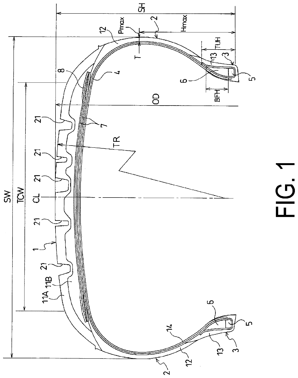
The present technology is about improving the braking performance of pneumatic tires on ice and reducing rolling resistance. The tire has a flat tread profile with increased ground contact width, which increases the braking performance on ice. The tire also has a reduced height of the bead filler, which reduces the vertical spring constant and causes the side wall portion to deflect, resulting in reduced energy loss and reduced rolling resistance. The tire's maximum width position should fall within a range of 50% to 60% of the tire cross-sectional height to reduce energy loss and rolling resistance. The rubber thickness at the tire maximum width position should fall within a range of 1 mm to 4 mm to further reduce energy loss and rolling resistance. The carcass layer should be turned up around the bead core from an inner side to an outer side of the tire with a turned-up height of 10% to 40% of the tire cross-sectional height to reduce the vertical spring constant, increase the ground contact area, and reduce rolling resistance.

Problems solved by technology

Thus, when the undertread rubber layer is increased in thickness, rolling resistance is likely to be degraded.
In view of this, even though rolling resistance is regarded as a minor problem for the pneumatic tire for use on icy and snowy roads in the related art, it has been demanded to reduce rolling resistance in recent years.

Method used


Image

  • Pneumatic Tire
  • Pneumatic Tire

Examples


example

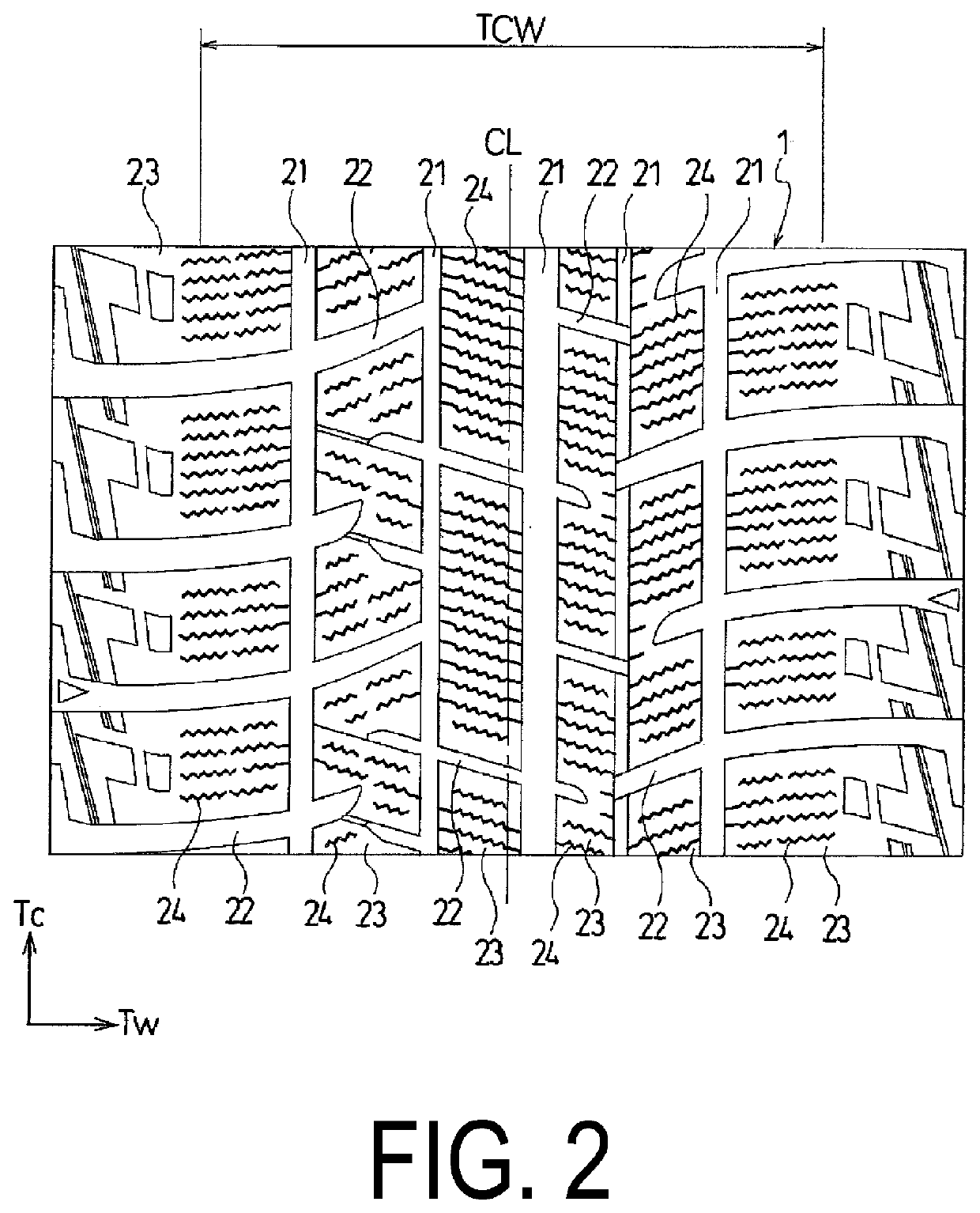
[0034]In a pneumatic tire in which each of the tires had a tire size of 205 / 60 R16 and included: a tread portion, a pair of sidewall portions, and a pair of bead portions, in which a carcass layer was mounted between the pair of bead portions, and the tread portion had a multilayer structure including a cap tread rubber layer and an undertread rubber layer, and in which grooves and sipes are formed in the tread portion, and a snow traction index STI based on those grooves and sipes was set 186 or more, a ratio of the tread radius TR with respect to the tire outer diameter OD (TR / OD×100%), a ratio of the ground contact width TCW with respect to the tire cross-sectional width SW (TCW / SW×100%), a ratio of the bead filler height BFH with respect to the tire cross-sectional height SH (BFH / SH×100%), the height H max at the tire maximum width position P max with respect to the tire cross-sectional height SH (H max / SH×100%), the rubber thickness T at the tire maximum width position P max, a...


PUM


Abstract

In a pneumatic tire including a tread portion, a pair of side wall portions, and a pair of bead portions, a carcass layer is mounted between the bead portions, the tread portion has a multilayer structure including a cap tread rubber layer and an undertread rubber layer, and a snow traction index is 180 or more. A tread radius in a meridian cross-section of the tread portion falls within a range of from 80% to 140% of a tire outer diameter, a ground contact width of the tread portion falls within a range of from 66% to 83% of a tire cross-sectional width, and a height of a bead filler is 40% or less of a tire cross-sectional height.

Description

TECHNICAL FIELD[0001]The present technology relates to a pneumatic tire suitable for use on icy and snowy roads and particularly relates to a pneumatic tire capable of improving braking performance on ice and reducing rolling resistance.BACKGROUND ART[0002]In general, in a pneumatic tire for use on icy and snowy roads, which is exemplified by a studless tire, a plurality of longitudinal grooves extending in a tire circumferential direction and a plurality of lateral grooves extending in a tire lateral direction are formed in a tread portion, and a number of blocks are defined by those longitudinal grooves and lateral grooves. Further, a plurality of sipes are formed in each of the blocks.[0003]The pneumatic tire as described above can exert excellent driving performance on ice and snow with the grooves and the sipes formed in the tread portion. In recent years, it has been further demanded to improve braking performance on ice.[0004]Further, the pneumatic tire for use on icy and sno...

Claims


Application Information

Patent Timeline
IPC IPC(8): B60C11/00B60C15/00B60C15/06B60C11/03B60C11/12
CPCB60C11/005B60C15/0027B60C15/0018B60C15/0603B60C2011/1254B60C11/1236B60C11/1204B60C2011/1213B60C11/0304Y02T10/86B60C11/0306B60C2011/0381B60C2011/0025B60C11/0083B60C3/04B60C11/0332B60C2013/007B60C2015/009B60C9/2009B60C2009/2016B60C2011/0016B60C11/1272B60C2015/061B60C2011/129B60C2011/0339B60C11/00B60C13/00B60C15/06B60C11/0327
Inventor CHAYA, HITOMI
Owner YOKOHAMA RUBBER CO LTD
Learn More