Feed conveying apparatus

a conveying apparatus and conveying technology, applied in the direction of animal feeding devices, transportation and packaging, transportation of animals, etc., can solve the problems of inability to efficiently and stably convey feed, the disk cable b>3/b> cannot be smoothly moved in the feed conveying path, and the bottom surface of the screw is cracked or holed, etc., to achieve the effect of suppressing the floating of the disk cable, improving the conveying efficiency, and improving the hygienic problems

Inactive Publication Date: 2009-01-08
FUJII SHOKAI
View PDF9 Cites 29 Cited by
  • Summary
  • Abstract
  • Description
  • Claims
  • Application Information

AI Technical Summary

Benefits of technology

[0007]The invention is, therefore, made in consideration of the above conventional problems in the feed conveying apparatus and it is an object of the invention to certainly prevent the occurrence of the trouble which is caused by the looseness of the disk cable and to efficiently and stably convey the feed by the disk cable without leaving the feed in the feed conveying path.
[0028]According to the ninth aspect of the invention, as for the rim, the interval between the elastic pads with which the disks are come into engagement is adjusted by increasing or decreasing the number of spacer plates to be fitted into the boss in accordance with the radius size of the disk of the disk cable. Therefore, for the disk cable which is used, the common driving wheels can be always used so as to be adjusted to the disks of various radius sizes without needing the different driving wheels every radius size of the disk. In the driving wheel, even if the disk guide groove of the elastic pad is abraded with the elapse of time, by removing the elastic pad from the boss, pulling out the spacer plates of the necessary number in accordance with a degree of the abrasion of the disk guide groove, and adjusting the interval between the elastic pads of the disk guide groove, the disk guide groove can be always easily adjusted to the disks. Consequently, upon driving of the disk cable, when the disk passes through the disk guide groove of the driving wheel, it is always fitted into the disk guide groove and smoothly come into engagement therewith out slipping, thereby enabling the rotating force to be accurately transferred.

Problems solved by technology

Thus, if such a motion is repeated, there occurs a conveyance trouble in which cracks or holes are formed in the bottom surface portion 2c with the elapse of time and the feed leaks from those gaps.
The disk cable 3 is fed while the disks 3a are strongly rubbing the inner wall surface of the curved pipe and the cable is subjected to an excessive load, so that its frictional resistance becomes an obstacle to the cable run and the disk cable 3 cannot be smoothly moved in the feed conveying path.
Due to those factors, hitherto, the feed cannot be efficiently and stably conveyed without leaving the feed in the feed conveying path in dependence on the disk cable 3.

Method used


Image

  • Feed conveying apparatus
  • Feed conveying apparatus
  • Feed conveying apparatus

Examples


first embodiment

[0061]The feed conveying apparatus A of the first embodiment has a pipe (p) constructed in a pipeline shape by providing a plurality of corner portions 12 in accordance with a setting layout of the feed suppliers (C) and couples the feed supplying apparatus (B) and each feed supplier (C) through the pipe (p). Each feed supplier (C) is communicated with the pipe (p) through a drop pipe 13 which is vertically and downwardly attached.

[0062]The pipe (p) forms a straight pipe portion by coupling a plurality of straight-pipe-shaped conveying pipes. The straight pipe portion is connected to the several corner portions 12. An endless feed conveying path is formed in the pipe (p). A disk cable (a) for feed conveyance is endlessly coupled and inserted in the hollow pipe. A cable driving unit 15 for driving the disk cable (a) is equipped for the pipe (p) on the way of the feed conveying path adjacent to the feed supplying apparatus (B). The corner portion 12 has a structure in which a corner f...

second embodiment

[0072]The feed conveying apparatus (A) of the second embodiment is characterized by the corner driving system in which the cable driving units 15 are provided in the corner portions 12 of the pipe (p), in each cable driving unit, the disks 20 of the disk cable (a) are come into engagement with the teeth (g) of the driving wheel 25 and the disk cable is wound around the wheel, and the same disk cable (a) is driven by a plurality of driving motors (m) in a sharing manner.

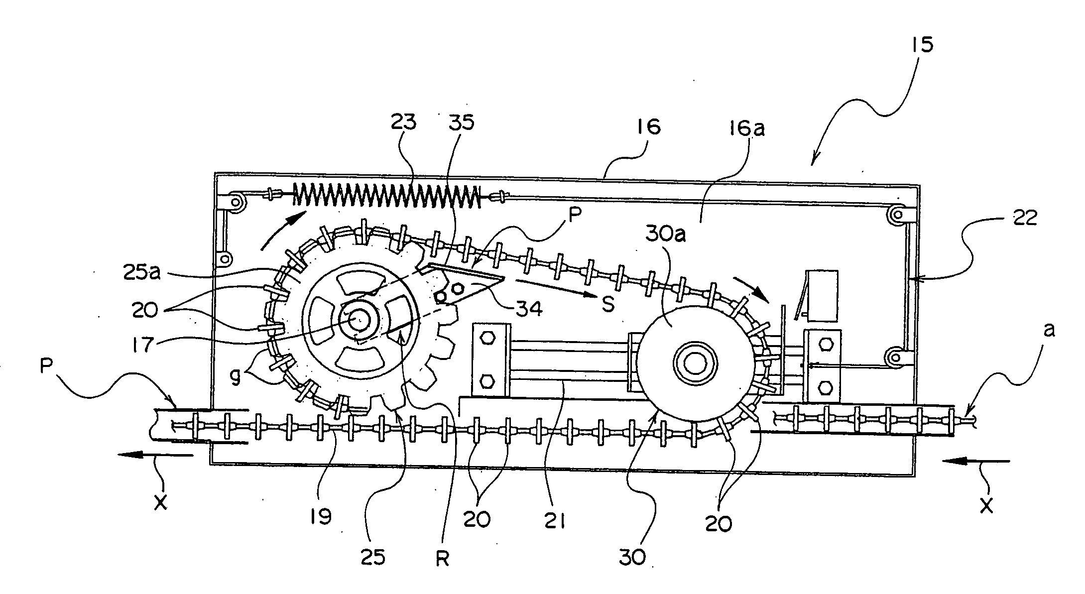
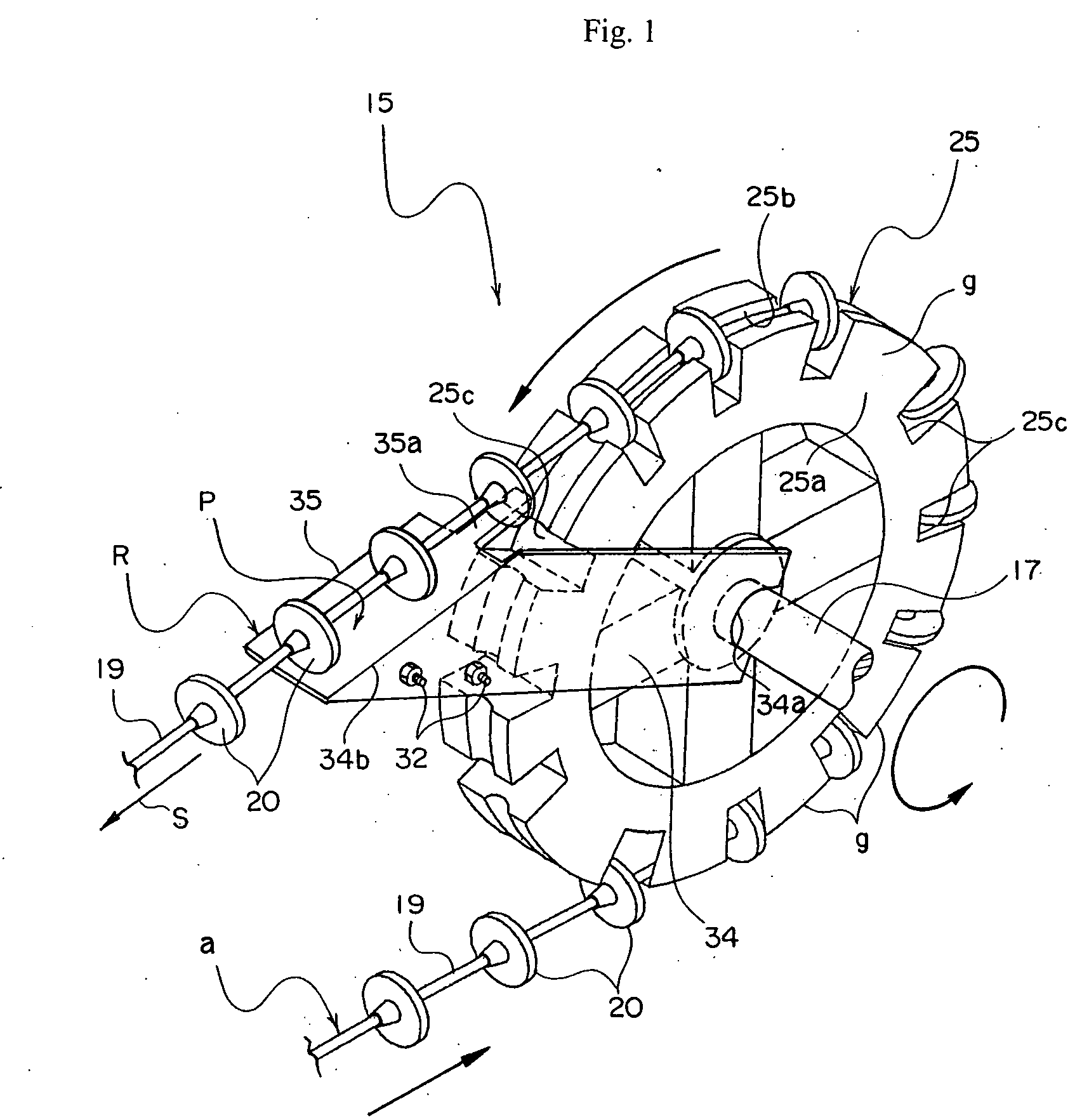
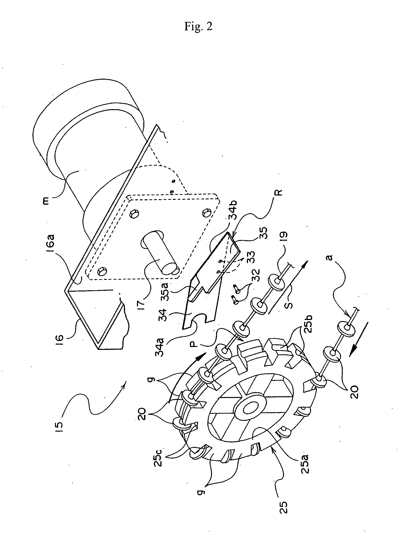
[0073]According to the cable driving unit 15 of the second embodiment, as shown in FIGS. 8 and 9, the driving motor (m) is externally attached to a bottom surface plate portion 14a of each circular corner cover 14. In the corner cover 14, the driving wheel 25 is directly coupled with the driving shaft 17 of the driving motor (m) and axially supported, the disks 20 of the disk cable (a) are come into engagement with the teeth (g) of the driving wheel 25, the disk cable is wound around the wheel, and the disk cable (a) ...

third embodiment

[0082]Also in the gutter conveying system, each cable driving unit 15 has a construction in which the looseness eliminating member (R) for guiding the feeding direction (S) of the disk cable (a) and eliminating its looseness is arranged at the feeding start position (P) of the driving wheel 45 where the disk cable (a) is fed out.

[0083]In the feed conveying apparatus (A) of the third embodiment, therefore, upon operating, in each corner portion 12, the driving motor (m) of the cable driving unit 15 is individually made operative to thereby rotate each driving wheel 25, the same disk cable (a) is run on the feed conveying path in the feed tub (q) by the driving motors (m) in a sharing manner, respectively. Therefore, in the feed conveying apparatus (A) of the third embodiment using the driving load sharing system as mentioned above, in a manner similar to the foregoing second embodiment, the disk cable (a) runs in the feed tub (q) with little load resistance. Thus, the conveying speed...


PUM


Abstract

There is provided a feed conveying apparatus in which the occurrence of a trouble due to a looseness of a disk cable is certainly prevented and feed is efficiently and stably conveyed into a feed conveying path by the disk cable without being left in the path.A cable driving unit has a looseness eliminating member for guiding the feeding direction of the disk cable and eliminating the looseness at a feeding start position where the disk cable is fed out from a tooth portion of the outer circumference of the driving wheel toward the downstream side in the tangential direction. The feed conveying path formed by a pipe or the like is equipped with a cable pressing metal fitting for guiding the disk cable along a bottom surface portion in the feed conveying path while suppressing the floating of the disk cable running in the feed conveying path from an upper position.

Description

BACKGROUND OF THE INVENTION[0001]The invention relates to a feed conveying apparatus constructed in such a manner that a disk cable to which a number of feed conveying disks are assembled at regular intervals by penetrating a cable through the centers of the disks is endlessly suspended and arranged in a feed conveying path formed by an endless pipe or the like and the disk cable is driven, thereby conveying feed for breeding cows, pig farming, chicken farming, or the like to a feed supplier side.[0002]Hitherto, as shown in FIG. 26, such a kind of feed conveying apparatus generally uses a single-driving unit system in which a disk cable 3 is endlessly coupled and inserted in a pipe 2 that is provided with several corner portions 2a are provided in accordance with a setting layout of a number of feed suppliers 1 and is endlessly formed and one driving unit 4 of the disk cable 3 is provided at a position on the way of a feed conveying path of the pipe 2. According to the single-drivin...

Claims


Application Information

Patent Timeline
Patent Type & Authority Applications(United States)
IPC IPC(8): B65G23/44
CPCA01K5/0208B65G23/44B65G19/14A01K5/0258
Inventor FUJII, KAZUMI
Owner FUJII SHOKAI
Why Eureka
Try Eureka