Optical Device

a technology of optical devices and flashing devices, applied in the field of optical devices, can solve the problems of limited available space, unsuitable for such use, and the flashing of zoom flashes described above with a focusing device, and achieve the effect of less sensitive to mechanical shock and precise adjustmen

Inactive Publication Date: 2009-01-08
SONY CORP
View PDF13 Cites 13 Cited by
  • Summary
  • Abstract
  • Description
  • Claims
  • Application Information

AI Technical Summary

Benefits of technology

[0024]An optical device according to the invention has no moveable parts that require precise adjustment, and it is therefore less sensitive to mechanical shock.
[0025]When taking a photograph of an object, e.g. a portrait photograph of a person, with background at a larger distance from the camera lens than the person, the central portion of the light-emitting element will illuminate the person, and the peripheral portion will illuminate the background. The central light emitting zone or zones can be controlled to emit light with a lower intensity than the zones in the peripheral portion, whereby both the person close to the camera and the more distant background can be more uniformly illuminated.

Problems solved by technology

In e.g. mobile communication devices, such as mobile telephones, small cameras are used, where the available space is limited.
A traditional zoom flash as described above with a focusing device that is moveable relative to the light source is not suitable for such use due to its space requirements.
Also this device is quite large and thus less suitable for small mobile devices.

Method used


Image

  • Optical Device
  • Optical Device
  • Optical Device

Examples


Embodiment Construction

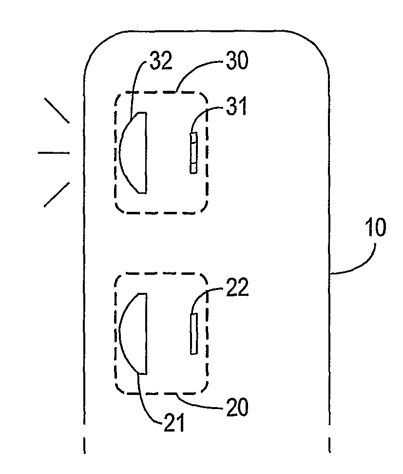
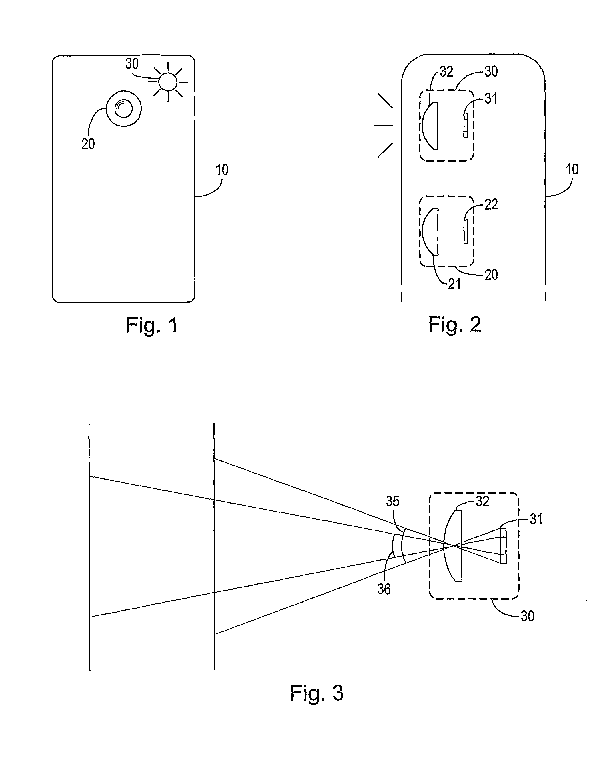
[0032]In FIGS. 1 and 2 is shown the contour of a mobile telephone 10 with a camera 20 or other means for taking photographic images and an illumination device 30 that can be controlled to emit light for illuminating an object to be photographed by the camera 20. The mobile telephone 10 has means for wireless voice communication, which are not shown.

[0033]The camera 20 comprises an imaging lens 21 arranged in an imaging relationship with a light sensitive element 22 so as to project light from the object onto the light sensitive element to form an image of the object thereon. In the illustrated example the light sensitive element 22 is e.g. a charge-coupled device (CCD), and the images taken are digital images. Alternatively, the light sensitive element comprises a film with a light sensitive emulsion on a carrier.

[0034]The digital camera 20 is capable of zooming, i.e. varying the opening angle, i.e. the spatial angle within which objects are imaged on the light sensitive element 22....


PUM


Abstract

An optical device for use with an imaging device for taking photographic images of an object includes a light emitting element capable of emitting light, and a lens arranged so as to direct light from the light emitting element to illuminate the object. The light emitting element may include at least two light emitting zones arranged so that light from the light emitting zones can be directed from the lens in respective corresponding spatial angles, and that the light emitting zones can be individually and selectively controlled to emit a controllable intensity of light.

Description

TECHNICAL FIELD OF THE INVENTION[0001]The invention relates to optical devices for use with an imaging device such as a camera for taking photographic images of an object and for illuminating the object when taking the image.DESCRIPTION OF RELATED ART[0002]Traditional analogue and digital cameras use a flash with a discharge tube and a lens, a concave mirror or other focusing device for directing the light from the discharge tube towards the object. Cameras having a lens with a variable focal length (zoom lens) can use a zoom flash, where the focusing device is moved relative to the discharge tube in dependence on the focal length of the camera lens, whereby the spreading angle of the beam of light from the flash is controlled to correspond to the imaging angle of the camera lens. At short focal lengths of the camera lens the flash is controlled to spread the light more than at long focal lengths, whereby substantially only the object that is being photographed is illuminated.[0003]...

Claims


Application Information

Patent Timeline
Patent Type & Authority Applications(United States)
IPC IPC(8): G02B27/40H01L33/00
CPCG03B15/02H04M1/22H04N5/23296H04N5/2256H04M2250/52Y10S362/80H04N23/56H04N23/69
Inventor WERNERSSON, MATS
Owner SONY CORP
Why Eureka
Try Eureka