

Apparatus for Manufacturing Molten Irons
- Summary
- Abstract
- Description
- Claims
- Application Information
AI Technical Summary
Benefits of technology
Problems solved by technology
Method used
Image

Examples
Embodiment Construction
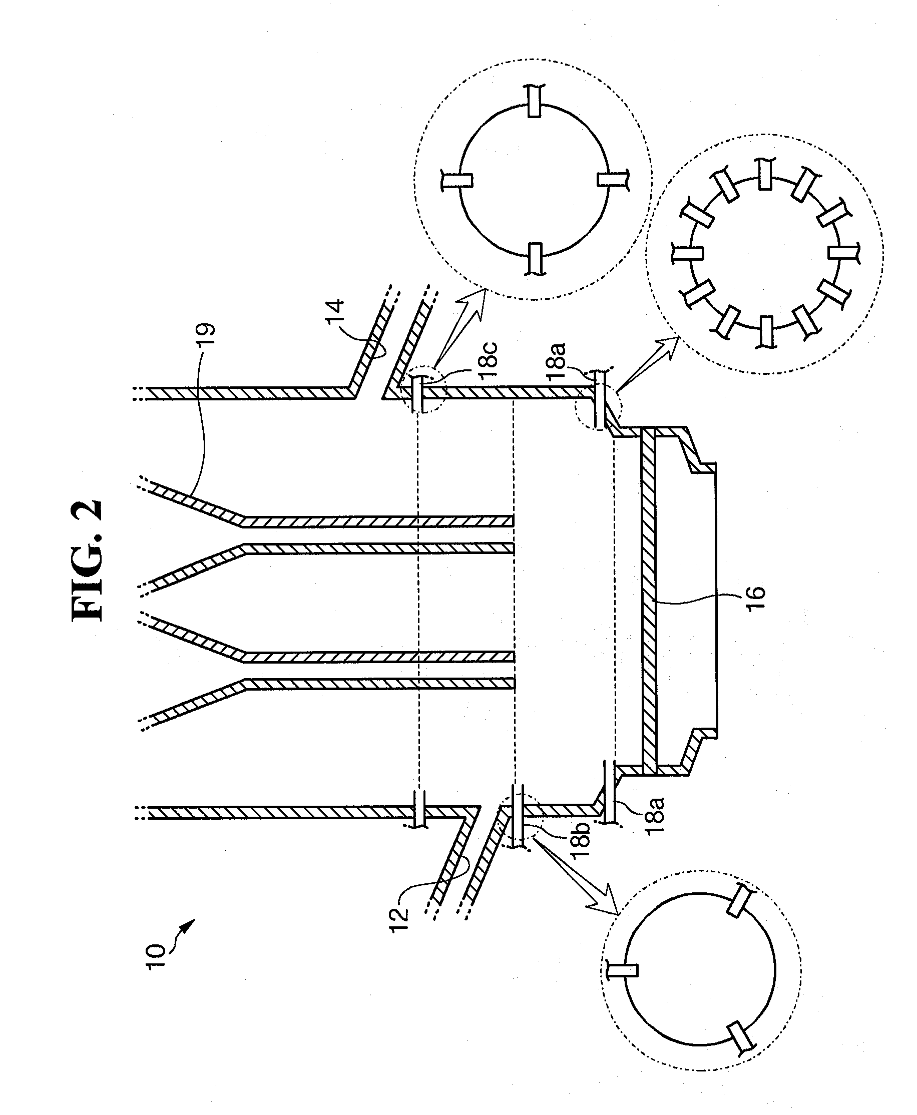
[0058]Twenty three gas injectors in total were installed in the experimental example. That is, sixteen gas injectors were installed at a height of 350 mm above the distribution plate, three gas injectors were installed at a height of 1100 mm thereabove, and four gas injectors were installed at a height of 1400 mm thereabove. The temperature was measured during the operation of the fluidized-bed reduction reactor. Further, the temperature of a fluidized-bed reduction reactor in which the gas injectors were not installed was measured as a comparative example.
[0059]FIG. 5 shows results of measurements of change of temperature in the experimental example and the comparative example, respectively. Referring to the drawing, the temperature of the fluidized-bed reduction reactor according to the experimental example rose at a constant rate as the operation proceeded, was maintained at a uniform temperature, and dropped at a constant rate as the operation ended.
[0060]On the other hand, in t...
PUM
| Property | Measurement | Unit |
|---|---|---|
| Height | aaaaa | aaaaa |
| Distance | aaaaa | aaaaa |
Abstract
Description
Claims
Application Information