
Light-emitting appartus

a technology of light-emitting apparatus and discharge tube, which is applied in the direction of discharge tube/lamp details, discharge tube luminescnet screens, discharge tube details, etc., can solve the problems of high energy loss in the light-emitting layer, inability to efficiently generate and inability to achieve high luminance white light efficiently

Inactive Publication Date: 2009-01-08
SUBARU CORP +1
View PDF2 Cites 7 Cited by
  • Summary
  • Abstract
  • Description
  • Claims
  • Application Information

AI Technical Summary

Benefits of technology

[0016]In accordance with the light emitting apparatus of the present invention, high luminance white light can be generated efficiently.

Problems solved by technology

However, while many developments have been made of highly luminous light emitters regarding light emitters that emit white light upon excitation by ultraviolet, as with light emitters widely used in general in fluorescent tubes, light emitters that emit white light by excitation with electrons have not yet presently been developed which emit at sufficiently high luminance.
Therefore, in the case such as that of FELs, if an attempt were made to produce white light by providing an anode with a light emitter that emits white light upon excitation, there would be a risk of causing much energy loss in the light emitter layer, making it difficult to efficiently generate high luminance white light.

Method used


Image

  • Light-emitting appartus
  • Light-emitting appartus
  • Light-emitting appartus

Examples


Embodiment Construction

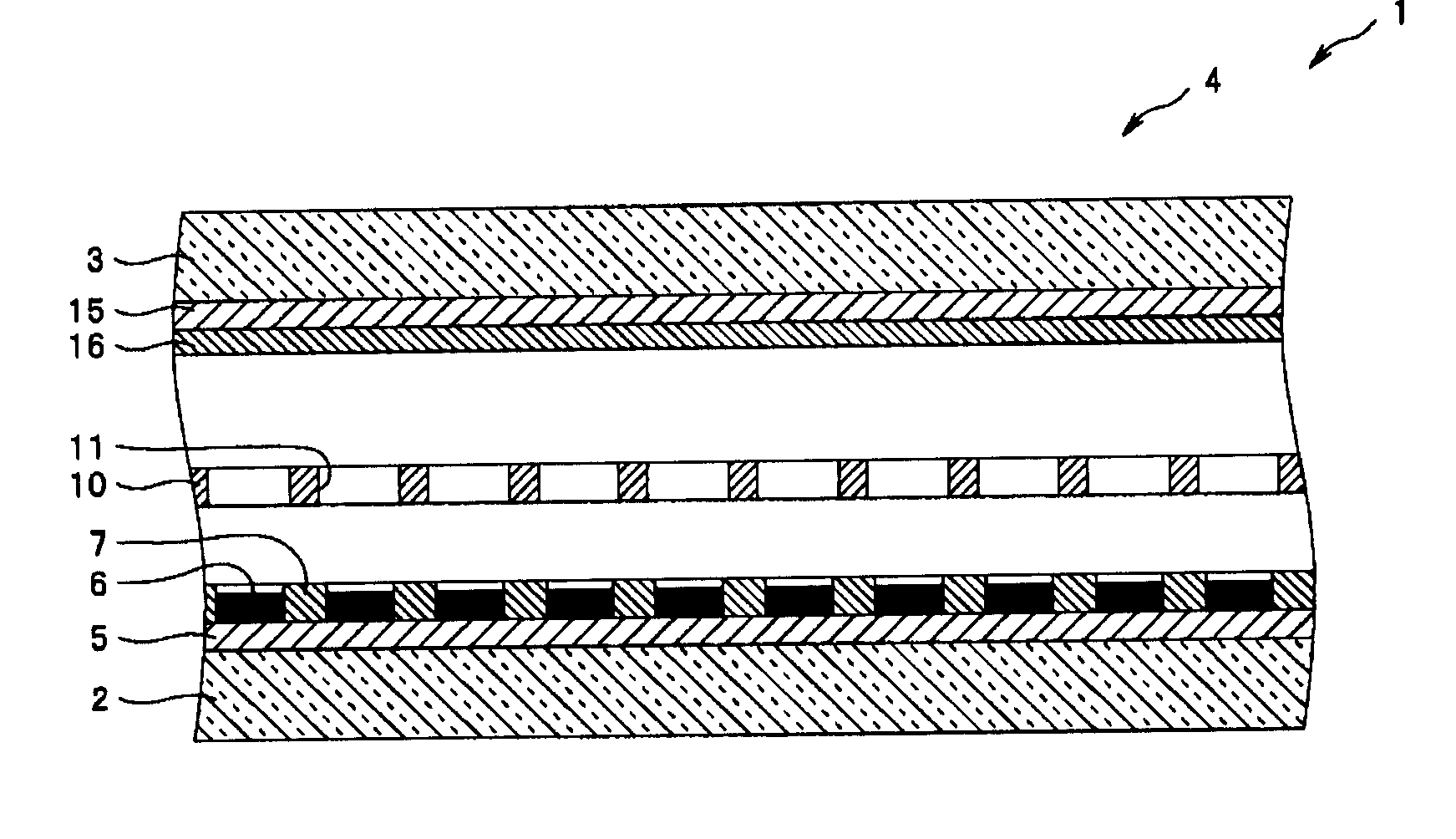
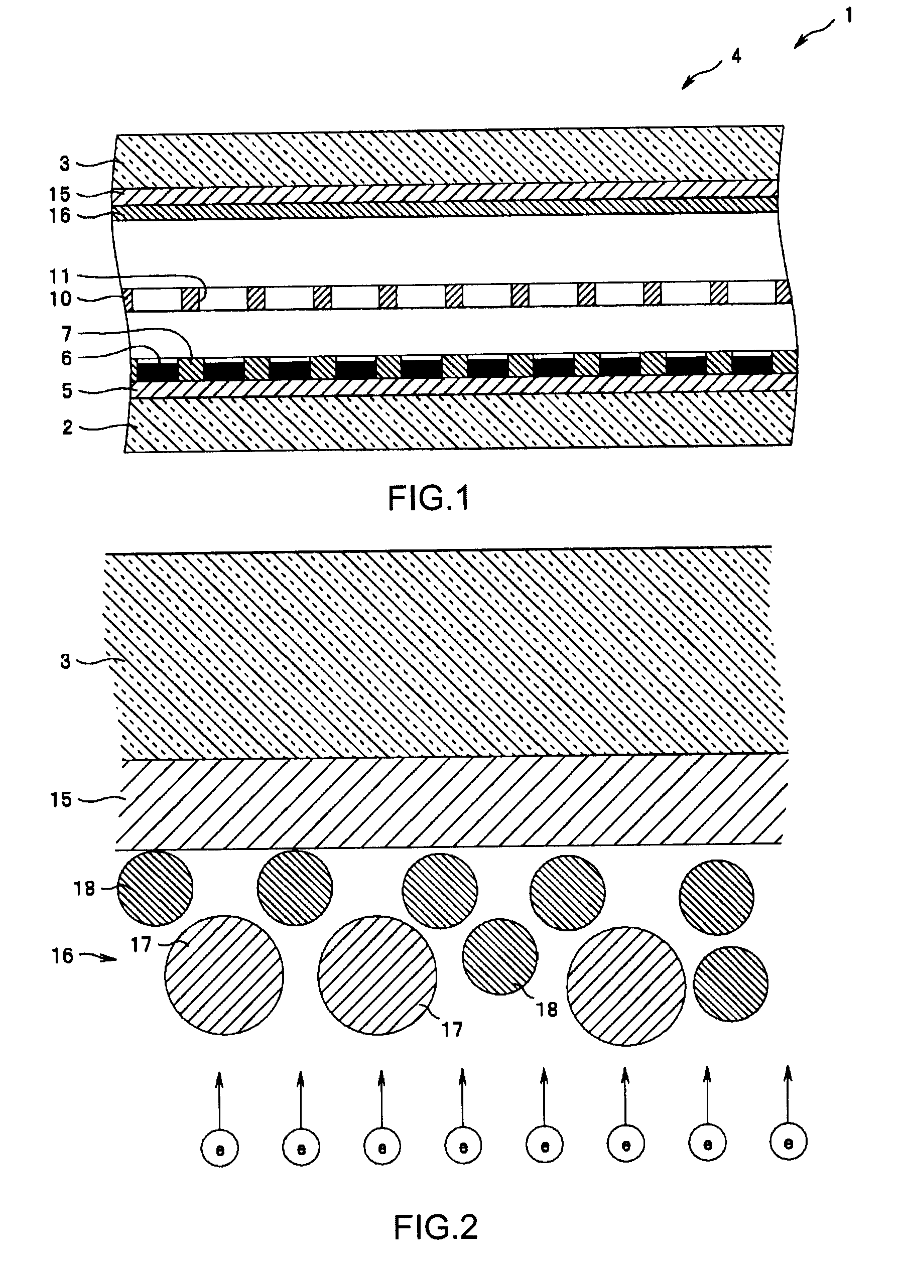
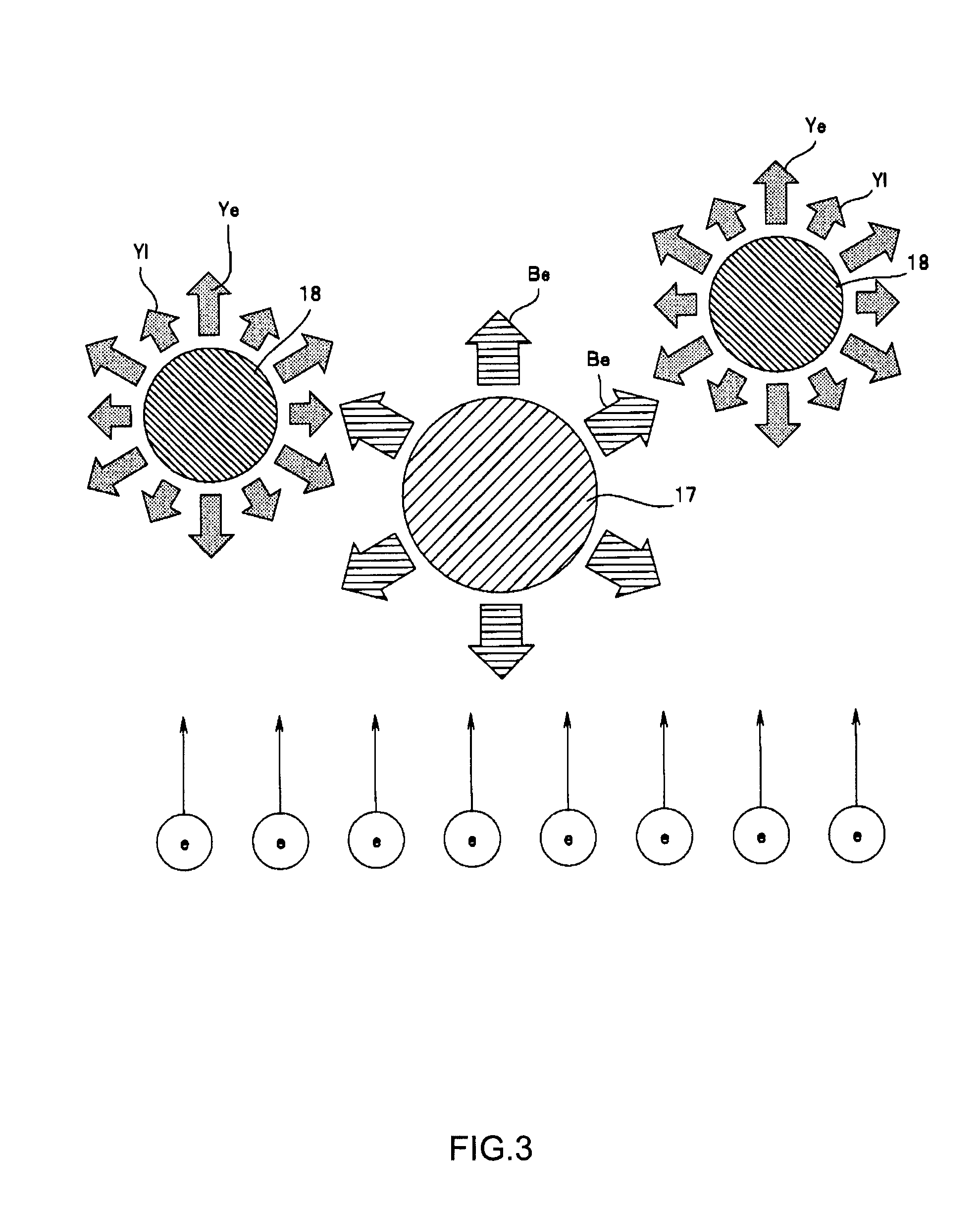
[0022]Hereinafter, embodiments of the present invention are explained with reference to the drawings. The drawings relate to an embodiment of the present invention: FIG. 1 is a basic construction view; FIG. 2 is an expanded schematic view of the light emitter layer; FIG. 3 is an explanatory view of light emission upon excitation of a blue light emitter and a yellow light emitter; FIG. 4 is a diagram showing luminance distribution of the light emitted by a blue light emitter unit, a yellow light emitter unit, and each light emitter of a mixed emitter thereof; FIG. 5 is a diagram showing the relationship between the weight ratio of the blue light emitter and yellow light emitter in a light emitter layer and luminance thereof.

[0023]As illustrated in FIG. 1, a light emitting apparatus 1 in the present embodiment is a light emitting apparatus used, for example, as a planar, field-emission type white illumination lamp, and has a basic construction in which a cathode 5, gate electrode 10, ...


PUM


Abstract

A light emitting apparatus capable of efficiently generating high luminance white light is provided. The present invention permits white light to be generated, without using low-emission efficiency white light emitters, by forming a light emitter layer 16 using a high-light emission efficiency blue light emitter and yellow light emitter. In this case, having at least a part of the blue light emitter particles 17 and at least a part of the yellow light emitter particles 18 exposed at a surface of the light emitter layer 16, respectively, allows both of such particles to be directly bombarded with electrons, thereby effecting a highly efficient electron excitation. Furthermore, the use of YAG or the like, as a yellow light emitter, which emits yellow light not only by electron excitation but also through photoexcitation by the blue light, permits said blue light to contribute to the emission of the yellow light, even when part of the blue light emitted by the blue light emitter particles, as it passes through the light emitter layer 16, is blocked by the yellow light emitter particles 18, whereby white light can be generated efficiently with a reduction in energy loss.

Description

CROSS REFERENCE TO RELATED APPLICATIONS[0001]This application claims priority under 35 U.S.C. 119 based upon Japanese Patent Application Serial No. 2007-175650, filed on Jul. 3, 2007 and Japanese Patent Application Serial No. 2008-165394, filed on Jun. 25, 2008. The entire disclosures of the aforesaid applications are incorporated herein by reference.FIELD OF THE INVENTION[0002]The present invention relates to a light emitting apparatus for generating white light by allowing a light emitter (fluorescent material) to emit light upon excitation by field-emitted electrons from a cold-cathode electron emission source.BACKGROUND OF THE INVENTION[0003]In recent years, as alternatives to the conventional light emitting apparatuses such as incandescent light bulbs, fluorescent lamps, and the like, there have been developed cold-cathode electron emission type light emitting apparatuses which involve impinging field-emitted electrons from a cold-cathode electron emission source at a high spee...

Claims


Application Information

Patent Timeline
Patent Type & Authority Applications(United States)
IPC IPC(8): H01J1/62
CPCH01J63/06H01J63/04
Inventor NAMBA, ATSUSHIARAKAWA, TOSHIYANAKAZATO, KUNIOTAKAHASHI, HISAYAENDO, TADASHIYAMAGUCHI, GOROIWASAKI, MINETO
Owner SUBARU CORP
Learn More