Holder, electrical supply, and RF transmitter unit for electronic devices

a technology for electronic devices and transmitters, applied in the direction of electrical apparatus construction details, electrical apparatus casings/cabinets/drawers, instruments, etc., can solve the problems of battery life sometimes a problem, speaker size, mp3 players typically playback sound for only one listener, etc., to achieve better signal, easy and semi-permanent adjustment, and strong and cleaner

Inactive Publication Date: 2009-01-08
BELKIN INT
View PDF77 Cites 46 Cited by
  • Summary
  • Abstract
  • Description
  • Claims
  • Application Information

AI Technical Summary

Benefits of technology

[0027]Some embodiments can provide a combined holder, electrical supply, and optional RF transmitter unit and / or an electronic accessory for an electronic device to be used, e.g., in a vehicle, having one or more of the following features and advantages: the unit may be mechanically mounted (desirably semi-permanently but otherwise, e.g., permanently, is also possible), e.g., to the vehicle, at only one point (e.g., by the cigarette lighter adapter); the unit is readily (i.e., rapidly and easily) coupled, e.g., to the vehicle (the mechanical and electrical connection is made merely by plugging the power acquisition sub-unit (comprising a cigarette lighter adapter) into the vehicle's cigarette lighter, the unit remains coupled to the vehicle even on bumpy roads and going around turns and resists rotation and other movement with respect to the vehicle, thereby keeping the electronic device in the desired position in the vehicle (in other words, the unit is stable); the unit is light-weight; the unit allows the position of the electronic device in the vehicle to be easily and semi-permanently adjusted (e.g., by means of a preferred gooseneck between the holder and the cigarette lighter adapter and / or by means of a preferred swivel joint between the gooseneck and the holder); the unit accommodates electronic devices of different sizes and holds them securely (e.g., by using different size clasps for different electronic devices), even on bumpy roads and going around turns; the unit can provide power from the vehicle's electrical system to the electronic device; the cigarette lighter adapter of the unit accommodates cigarette lighters of different sizes and shapes; the unit converts the data output signal received from the electronic device (as is or as it may be modified) to an RF signal, which is then transmitted to the vehicle's audio system by using the gooseneck, when made of metal, as the broadcast antenna, the gooseneck thus functioning as an adjustable, repositionable mechanical support and connecting element and as an electronic signal transmission element, thereby providing a better signal to the vehicle's audio system; the unit allows the user to select the audio mode of the signal; the unit produces a stronger and cleaner (e.g., more accurate) signal, e.g., to provide or facilitate a higher signal-to-noise ratio in the audio output; the unit allows the carrier frequency of the RF transmitter to be changed easily and rapidly and has a number of pre-sets for storing different carrier frequency information so that the unit can easily and rapidly be switched from one available pre-determined carrier (broadcast) frequency to another (e.g., by depressing the button that has been pre-programmed by the user to the desired one of the user pre-determined carrier frequencies); the unit allows the user to view the carrier frequency and audio mode information on a video display; a one-piece resilient protective membrane covers all of the buttons in some embodiments, thereby keeping dirt from entering the mechanism; the RF transmitter can be releasably held in the holder; both the electronic device and RF transmitter can be removed from the holder and coupled directly to each other and removed (if desired) from the vicinity of the rest of the unit (thereby allowing the transmitter to broadcast the RF signal (e.g., FM signal) to another RF receiver (e.g., in the user's home or office or in another vehicle equipped with a holder and power acquisition sub-unit unit of this invention; and the unit is sleek and modern looking.

Problems solved by technology

Battery life is sometimes a problem.
Another limitation is that these MP3 players typically playback sound for only one listener at a time (e.g., via headset or ear phones).
Even if the MP3 player is equipped with a speaker, the player's small size and light-weight design limit the size of the speaker, which tends to make the speaker inadequate for transmitting music to a group of people, e.g., in a vehicle.
However, current FM transmission systems are often unstable and provide weak FM signals, which can result in loss of signal or constant static hiss in the background.
In such known FM transmission systems, the FM signal strength is sometimes weakened or lost because of inefficient antenna design (e.g., concerning its size, shape, and / or location).
The current devices available, however, are often bulky, mechanically unstable, lack versatility, produce weak FM signals, yield noisy audio output from the FM receiver (e.g., audio output with noticeable hiss), and sacrifice user comfort and convenience.
Another common problem with MP3 accessories is that the accessories are designed to be compatible with only one or a very limited number of MP3 players.
That is, an MP3 accessory designed to work with the Apple iPod® MP3 player is not compatible with the Apple iPod® Mini MP3 player, the Apple iTouch® MP3 player or the Apple iPhone®.
Usually, the incompatibility is caused by the MP3 accessories inability to physically couple to the second MP3 player.
Furthermore, ever if a holder is designed to work with a specific accessory the holder cannot usually physically coupled to the accessory when the accessory is inside of a protective case.

Method used


Image

  • Holder, electrical supply, and RF transmitter unit for electronic devices
  • Holder, electrical supply, and RF transmitter unit for electronic devices
  • Holder, electrical supply, and RF transmitter unit for electronic devices

Examples


third embodiment

[0055]FIG. 23 is a front elevational view of a third embodiment, with an iPod mini MP3 player attached;

fourth embodiment

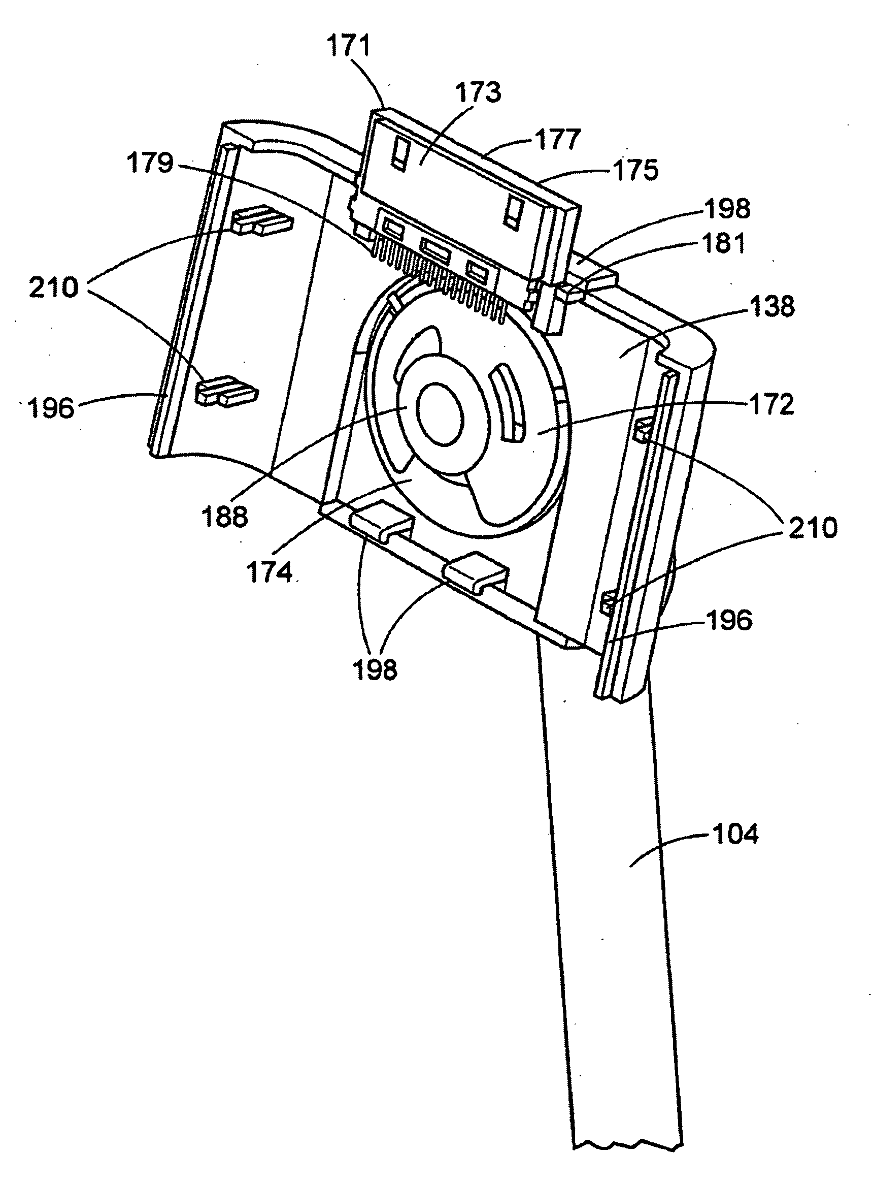
[0056]FIG. 24 is a front perspective representational view of the electronic device;

[0057]FIG. 25 is a front perspective, representational view of FIG. 24 attached to a media player, according to the fourth embodiment of the electronic device;

[0058]FIG. 26 is a front perspective, representational view of the electronic device of FIG. 24, where the side supports are uncoupled from the electronic device, according to the fourth embodiment;

[0059]FIG. 27 is a front perspective view of two pairs of side supports for the electronic device, according to the fourth embodiment;

[0060]FIG. 28 is a block diagram of an audio system of the electronic device of FIG. 24, according to the fourth embodiment;

fifth embodiment

[0061]FIG. 29 is a front perspective representational view of the electronic device;

[0062]FIG. 30 is a right-side view of the electronic device of FIG. 29, according to the fifth embodiment;

[0063]FIG. 31 is a front perspective view of four side supports for the electronic device, according to the fifth embodiment;


PUM


Abstract

In one embodiment, an electronic accessory for coupling electronic devices to an external power supply includes: (a) a holder having: (1) a cradle section configured to couple to at least two of the electronic devices, the cradle section comprising a power coupling; and (2) two or more side supports, each of the two or more side supports configured to removably couple to the cradle section; and (b) a power unit electrically coupled to the power coupling and configured to removably couple to the external power supply. At least a first one of the two or more side supports is configured to provide support to a first one of the electronic devices when the first one of the electronic devices is coupled to the cradle section. At least a second one of the two or more side supports is configured to provide support to a second one of the electronic devices when the second one of the electronic devices is coupled to the cradle section. Other embodiments are disclosed in this application.

Description

CROSS-REFERENCE TO RELATED APPLICATIONS[0001]This application claims the benefit of U.S. Provisional Application No. 60 / 959,057, filed Jul. 10, 2007 and is a continuation-in-parts of U.S. patent application Ser. No. 11 / 842,921, filed Aug. 21, 2007, which is a continuation of U.S. Pat. No. 7,292,881, filed Sep. 8, 2004. U.S. Provisional Application No. 60 / 959,057, U.S. patent application Ser. No. 11 / 842,921, and U.S. Pat. No. 7,292,881 are incorporated herein by reference.BACKGROUND OF THE INVENTION[0002]1. Field of the Invention[0003]This invention relates to accessories for electronic devices, particularly media players (e.g., portable MP3 players). More specifically, the invention relates to an electronic device with supports for holding the media players and a method of use of the same.[0004]2. Description of the Background[0005]Numerous types of electronic devices are known, many of which are portable, for example, mobile (or cellular) phones, laptop computers, and audio playbac...

Claims


Application Information

Patent Timeline
Patent Type & Authority Applications(United States)
IPC IPC(8): H05K5/00
CPCB60R2011/0005B60R2011/0054H04M1/6091H04B1/3877H04M1/6075B60R2011/0075
Inventor NEU, THORBENRAZO, VINCENTJACKSON, SCOTT
Owner BELKIN INT
Why Eureka
Try Eureka