Compact high voltage x-ray source system and method for x-ray inspection applications

a high-voltage x-ray and x-ray inspection technology, which is applied in the direction of x-ray tube vessels/containers, electrical devices, electric discharge tubes, etc., can solve the problems of large distances, thick insulation, and insufficient electrical insulation between the housing and the electrode at significantly higher voltages, so as to achieve low power consumption, small size, and low weight

Active Publication Date: 2009-01-08
NEWTON SCI
View PDF3 Cites 95 Cited by
  • Summary
  • Abstract
  • Description
  • Claims
  • Application Information

AI Technical Summary

Benefits of technology

[0009]A general object of the present invention is to provide a compact, self-shielded x-ray source for applications in which small size, low weight, and low power consumption are important.

Problems solved by technology

In such conventional systems, however, the voltages of the x-ray sources have been generally limited because of the size requirements for the x-ray tube and the high voltage power supply, as well as the associated electrical insulation and radiation shielding requirements.
Further, providing sufficient electrical insulation between the housing and electrodes at significantly higher voltages also requires larger distances and thicker insulation.

Method used


Image

  • Compact high voltage x-ray source system and method for x-ray inspection applications
  • Compact high voltage x-ray source system and method for x-ray inspection applications
  • Compact high voltage x-ray source system and method for x-ray inspection applications

Examples


Embodiment Construction

[0020]The following description may be further understood with reference to the accompanying drawings in which:

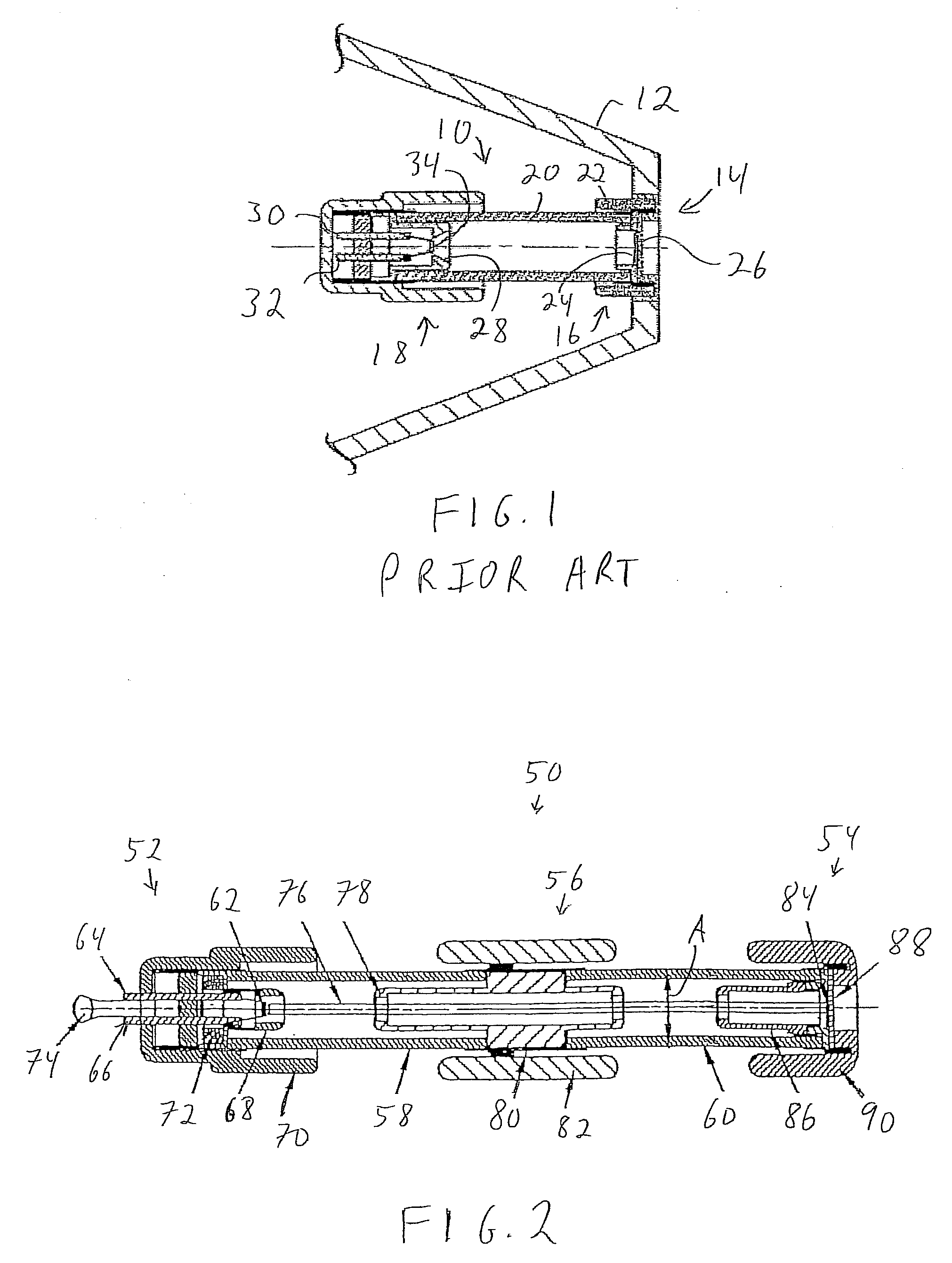
[0021]FIG. 1 shows an illustrative diagrammatic sectional side view of a conventional x-ray tube;

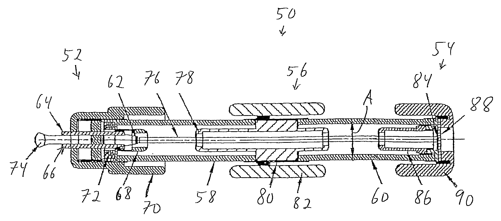
[0022]FIG. 2 shows an illustrative diagrammatic sectional side view of a bipolar x-ray tube having a transmission end-window in accordance with an embodiment of the invention;

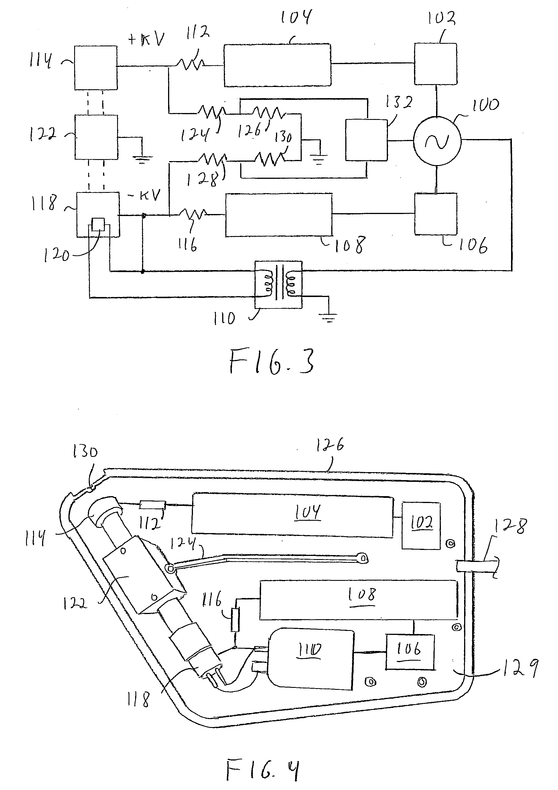
[0023]FIG. 3 shows an illustrative diagrammatic view of electrical components in a hand-held x-ray source system in accordance with an embodiment of the invention;

[0024]FIG. 4 shows an illustrative diagrammatic plan view of physical components in a hand-held x-ray system in accordance with an embodiment of the invention;

[0025]FIG. 5 shows an illustrative diagrammatic isometric view partial view of an anode end of a bipolar x-ray tube within a housing in accordance with an embodiment of the invention;

[0026]FIG. 6 shows an illustrative diagrammatic isometric view partial view of an anode end of a bipolar x-ra...


PUM


Abstract

An x-ray system is disclosed that includes a bipolar x-ray tube. The bipolar x-ray tube includes two insulators that are separated by an intermediate electrode in an embodiment, wherein each insulator forms a portion of an outer wall of a vacuum envelope of the bipolar x-ray tube surrounding at least a portion of a path of an electron beam within the vacuum envelope. In further embodiments, the bipolar x-ray tube includes a first electrode at a positive high voltage potential with respect to a reference potential, a second electrode at a negative high voltage potential with respect to the reference potential, and an x-ray transmissive window that is at the positive high voltage potential.

Description

PRIORITY[0001]This application claims priority to U.S. Provisional Patent Application Ser. No. 60 / 948,111 filed Jul. 5, 2007.FIELD OF THE INVENTION[0002]The present invention relates to systems and methods for providing compact X-ray sources for use in field portable or hand-held x-ray analytical instruments, and relates in particular to the design and construction of low power high voltage x-ray sources for use in field portable or hand-held x-ray analytical instruments.BACKGROUND[0003]Interest in the measurement of material properties using x-ray techniques has resulted in the development of compact, low power consumption x-ray sources for portable x-ray analytical instruments. Examples of such instruments are the hand-held x-ray fluorescence analyzers currently available from companies such as ThermoFisher Scientific Inc., Niton Analyzers, of Billerica, Mass., InnovX Systems of Woburn, Mass., and Oxford Instruments Company of Oxon, United Kingdom. In such conventional systems, ho...

Claims


Application Information

Patent Timeline
Patent Type & Authority Applications(United States)
IPC IPC(8): H01J35/18H01J35/00
CPCH01J2235/02H01J2235/087H05G1/10H05G1/06H01J2235/12H01J35/116
Inventor KLINKOWSTEIN, ROBERT E.SHEFER, RUTH E.
Owner NEWTON SCI
Why Eureka
Try Eureka