
Sensor-Incorporated Wheel Support Bearing Assembly

Inactive Publication Date: 2009-01-08
NTN CORP
View PDF5 Cites 4 Cited by
  • Summary
  • Abstract
  • Description
  • Claims
  • Application Information

AI Technical Summary

Benefits of technology

[0008]In view of the foregoing, an object of the present invention is to provide a wheel support bearing assembly of a type in which loads acting on the wheel support bearing assembly can be highly accurately and stably detected with a minimized number of sensors and in which the load sensor unit can be mounted compactly in an automotive vehicle.
[0010]According to this construction, since the tapered ring is secured to the inner member and the displacement sensor confronting the tapered ring is mounted on the outer member, the distance between the displacement sensor and the ring, which changes when the distance between the inner and outer members changes as a result of the load acting on the wheel support bearing assembly, can be detected by the displacement sensor. Change of the distance detected by the displacement sensor includes a displacement component acting on a radial direction and a displacement component acting in a thrust direction since the displacement sensor is so arranged as to confront the tapered outer peripheral surface of the ring. Because of this, it is easy to remove influences which may be bought about by temperature-dependent thermal expansion and shrinkage of the bearing element and there is no need to use a temperature sensor. Accordingly, the load acting on the wheel support bearing assembly can be accurately detected with a minimized number of sensors. As described above, since the displacement sensor is mounted in the wheel support bearing assembly with the number of sensors minimized, the load sensor unit including the displacement sensor can be mounted compactly in the automotive vehicle and the load acting on the wheel can be detected stably.
[0013]In such case, since signals obtained from four to eight sensor elements of the displacement sensor are used to determine the load, it is possible to achieve a load detection with high accuracy. Even in this case, since the displacement sensor is arranged so as to confront the tapered ring in radial and thrust directions, it is quite easy to remove influences which may be brought about by thermal expansion and shrinkage of the bearing elements resulting from temperature change.
[0015]The displacement sensor of the reluctance type is excellent in detection accuracy. In the case of the displacement sensor of the reluctance type, the cost of an electric circuit disposed downstream of the displacement sensor for the purpose of signal processing is high. On the other hand, the cost can be reduced if the magnetic detecting element is employed in the form of, for example, a Hall element.

Problems solved by technology

While the automobile traveling safety precaution is hitherto generally taken by detecting the rotational speed of the wheel, but it is not sufficient with the detection of only the rotational speed of the wheel and, therefore, it is required to achieve an improved safety control with the use of other sensor signals.
Also, even in the case of the uneven live load, the loads acting on those wheels tend to become uneven.
However, no space for installation of the load sensor for detecting the load acting on the respective vehicle wheel is available and, therefore, the attitude control through the detection of the load can hardly be realized.
Thus, the number of component parts (sensors) to be added for the measurement of those loads is increased and, therefore, it is unavoidable to increase the cost and the weight of the bearing assembly.
Also, the use of the increased number of the sensors eventually results in increase of the size of a detecting circuit and / or a controller for those sensors, unnecessarily accompanied by increase of the cost and the weight.
For those reasons, the bearing assembly disclosed in any one of the above discussed patent documents is ineffective to accomplish reduction in cost and weight, both of which have been desired for in the wheel support bearing assembly.

Method used


Image

  • Sensor-Incorporated Wheel Support Bearing Assembly
  • Sensor-Incorporated Wheel Support Bearing Assembly
  • Sensor-Incorporated Wheel Support Bearing Assembly

Examples


Embodiment Construction

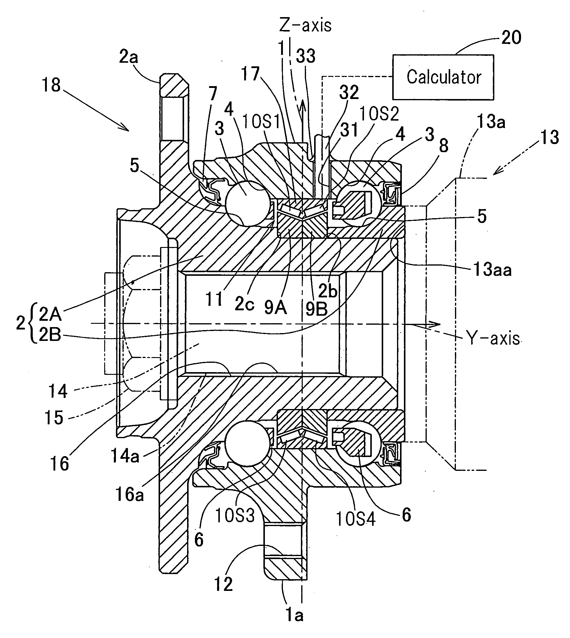
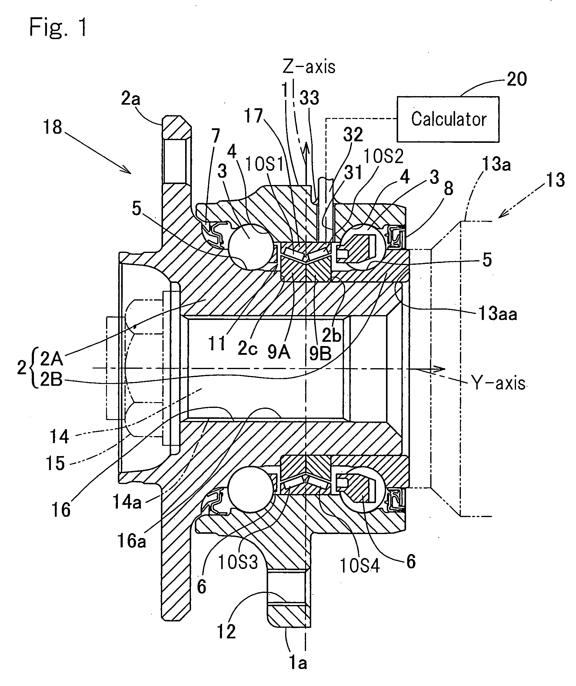
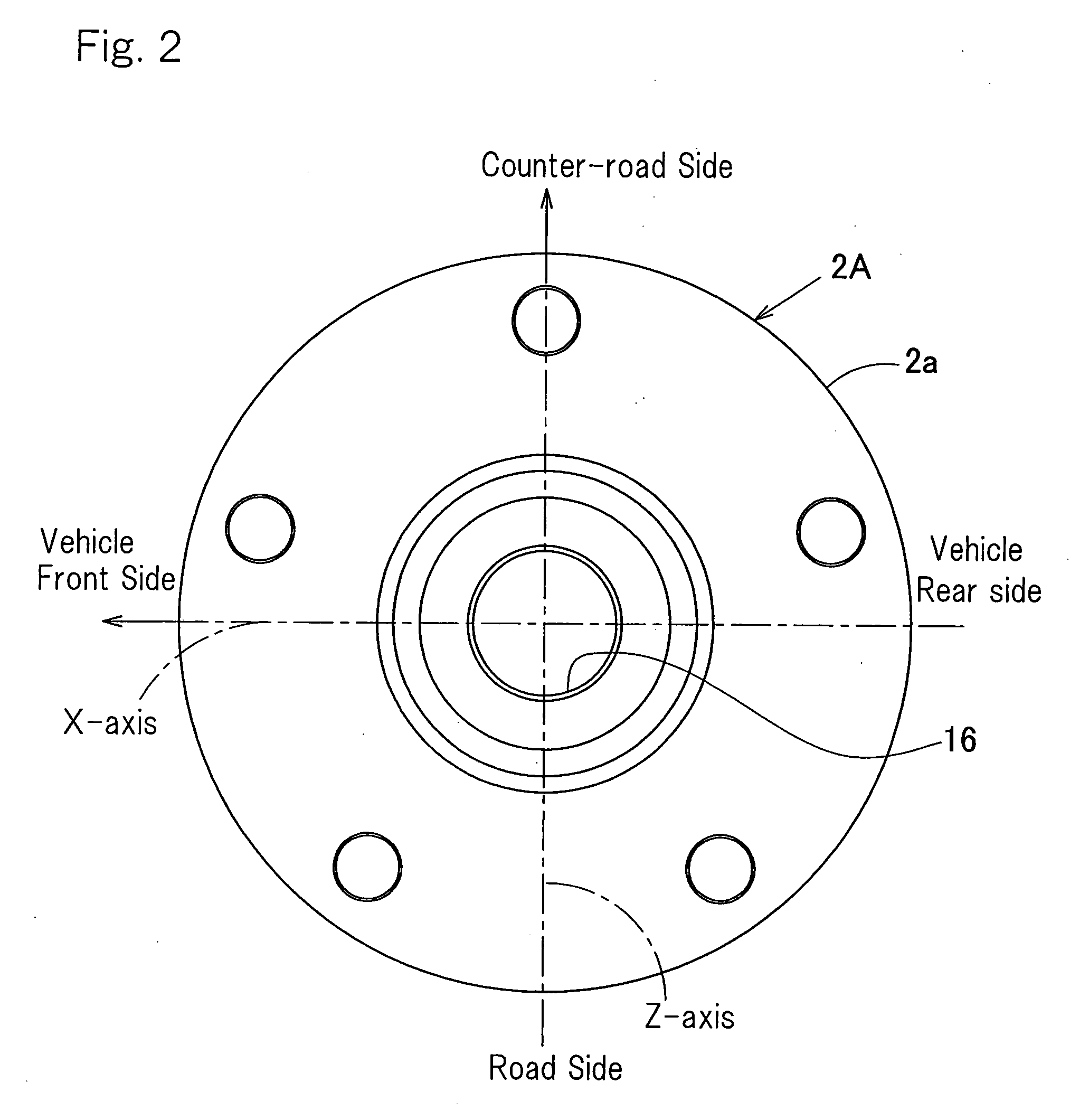
[0035]A first preferred embodiment of the present invention will be described with particular reference to FIGS. 1 to 17. This first embodiment is directed to a wheel support bearing assembly for rotatably supporting a drive wheel of an automotive vehicle, which assembly is an inner rotating type of a third generation model. It is to be noted that in the specification herein set forth, the terms “outboard” and “inboard” represent one side of the vehicle body away from the longitudinal center of the vehicle body and the other side of the vehicle body close to the longitudinal center of the vehicle body, respectively. For example, in FIGS. 1 and 3, a left portion represents the outboard side while a right portion represents the inboard side.

[0036]The wheel support bearing assembly 18 includes an outer member 1 having an inner peripheral surface formed with a plurality of, for example, two, rows of raceway surfaces 4, an inner member 2 having an outer peripheral surface formed with rac...


PUM


Abstract

A sensor-incorporated wheel support bearing assembly (18) includes an outer member (1) having an inner peripheral surface formed with double rows of raceway surfaces (4), an inner member (2) having an outer peripheral surface formed with raceway surfaces (5) opposed to the raceway surfaces (4) in the outer member (1), and double rows of rolling elements (3) interposed between the raceway surfaces (4) and (5) in the outer and inner members (1) and (2). Rings (9A) and (9B) each having an outer peripheral surface tapered is secured to the inner member (2). A displacement sensor (10) confronting the tapered outer peripheral surfaces of the rings (9A) and (9B) is mounted on the outer member (11) or a member (17) rigidly secured to the outer member (1) for measuring the distance between such displacement sensor (10) and the rings (9A) and (9B).

Description

FIELD OF THE INVENTION[0001]The present invention relates to a wheel support bearing assembly equipped with a sensor, for example, a load sensor for detecting a load imposed on a bearing portion of the wheel.BACKGROUND ART[0002]For safety travel of an automotive vehicle, the wheel support bearing assembly equipped with a sensor for detecting the rotational speed of one of automotive wheels has hitherto been well known in the art. While the automobile traveling safety precaution is hitherto generally taken by detecting the rotational speed of the wheel, but it is not sufficient with the detection of only the rotational speed of the wheel and, therefore, it is required to achieve an improved safety control with the use of other sensor signals.[0003]In view of this, it may be contemplated to achieve an attitude control based on the detection of a load acting on each of wheels during travel of an automotive vehicle. By way of example, a large load acts on the outside wheels during the c...

Claims


Application Information

Patent Timeline
IPC IPC(8): F16C33/30
CPCB60B27/0005B60B27/0068B60B27/0094G01L5/164F16C19/52F16C2326/02G01L5/0023F16C19/186F16C19/522
Inventor OZAKI, TAKAYOSHIISHIKAWA, TOMOMINISHIKAWA, KENTAROU
Owner NTN CORP
Learn More