Fluid transporting device

Inactive Publication Date: 2009-01-08
EBM PAPST ST GEORGEN & -
View PDF7 Cites 11 Cited by
  • Summary
  • Abstract
  • Description
  • Claims
  • Application Information

AI Technical Summary

Benefits of technology

[0008]It is therefore an object of the invention to make available a novel arrangement, for conveying fluids, which conserves both energy and space.
[0009]According to the invention, this object is achieved by connecting a pump wheel to a first permanent magnet, providing a “partitioning can” hermetically separating the pump from electrical drive components but permitting magnetic coupli

Problems solved by technology

These drives require energy and also a fairly large

Method used


Image

  • Fluid transporting device
  • Fluid transporting device
  • Fluid transporting device

Examples


Embodiment Construction

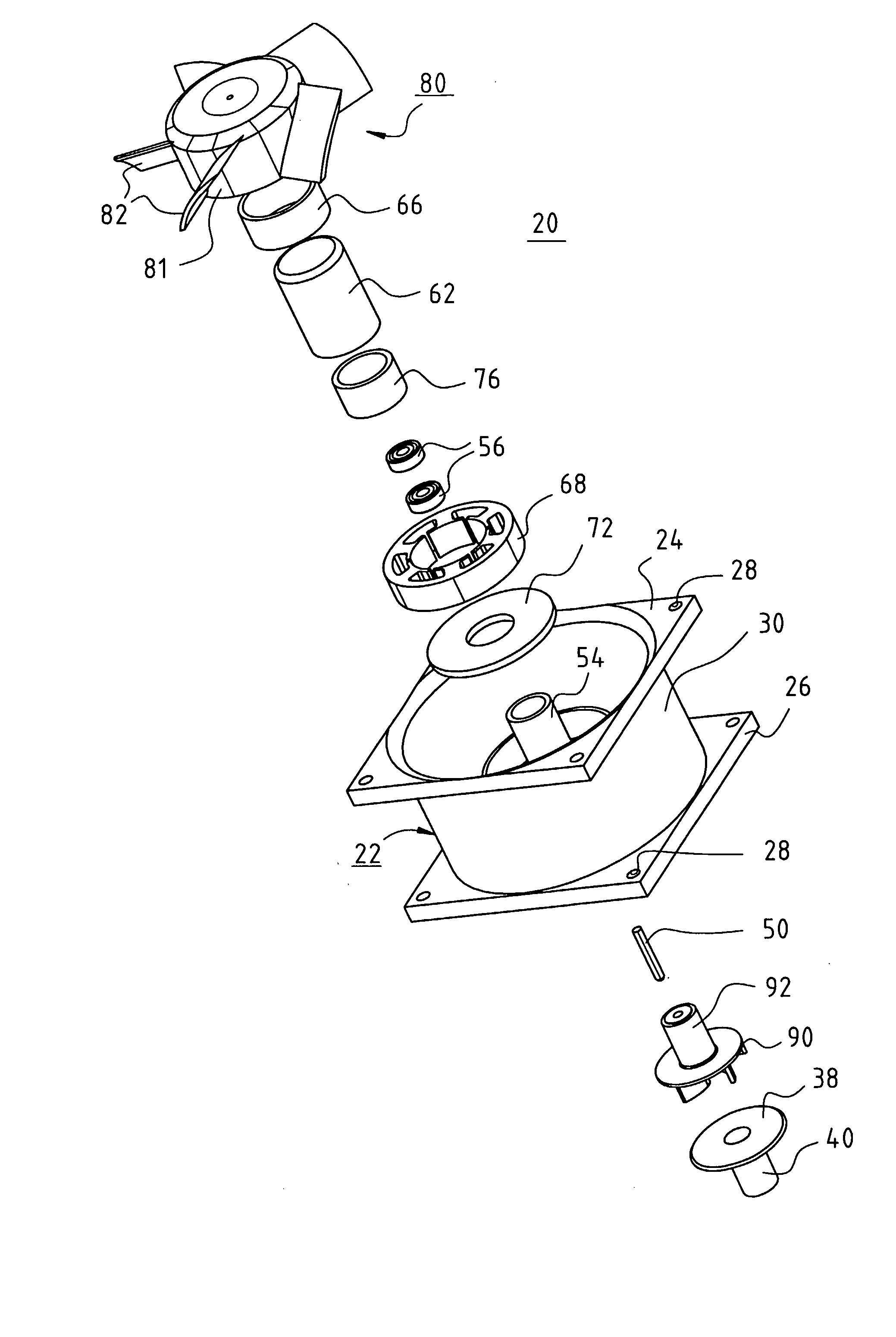
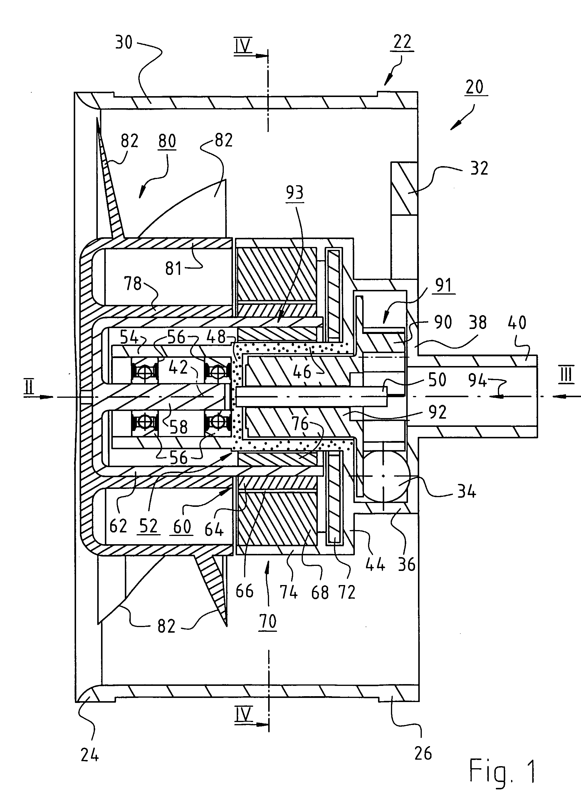
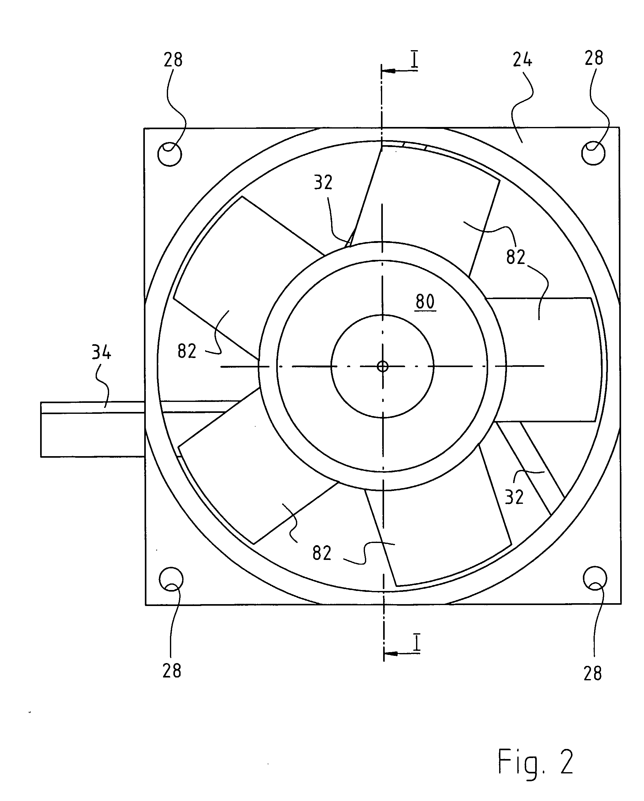
[0023]FIG. 1 is a longitudinal section through an arrangement 20 according to the present invention. Said arrangement has externally an approximately cylindrical fan housing 22 having two flanges 24, 26 (FIGS. 5 and 6), at each of whose corners a mounting hole 28 is located, and which flanges are connected to one another by a tubular part 30.

[0024]According to FIGS. 3 and 5, flange 26 is connected, by means of two obliquely extending struts or spokes 32 and by means of a sub-portion of an outlet fitting 34, to cylindrical part 36 of a pump housing that, in the completed state, is closed off by a cover 38 on which an inlet tube 40 is located. Cover 38 can be connected, for example by an adhesive connection, by plastic welding, or by means of an O-ring seal, in liquid-tight fashion to part 36.

[0025]Part 36 transitions, on its left side in FIG. 1, into a portion 44 extending perpendicular to a rotation axis 42, which portion transitions on its radially inner side into a cylindrical par...


PUM


Abstract

An arrangement for conveying fluids has a fluid pump (91) implemented in the manner of a centrifugal pump, having a pump wheel (90) that is connected to a first permanent magnet (92). The arrangement further has an electronically commutated internal-rotor motor (70) having a stator (68), inside which stator is rotatably arranged a rotor (60) that is in turn connected to a second permanent magnet (76; 140) that coacts with the first permanent magnet (92) in the manner of a magnetic coupling (93). The arrangement also has a partitioning can (52) that separates the first permanent magnet (92) of the magnetic coupling (93), which magnet is arranged inside said partitioning can (52), in fluid-tight fashion from the second permanent magnet (76; 140) arranged outside the partitioning can (52), the stator (68) of the internal-rotor motor (70) being arranged substantially in the same drive plane as the magnetic coupling (93) and radially outside the latter.

Description

CROSS-REFERENCE[0001]This application is a section 371 of PCT / EP2005 / 007772, filed 16 Jul. 2005 and published 16 Mar. 2006 as WO 2006 / 27043-A1 and further claims priority from German application DE 20 2004 014 417.4, filed 10 Sep. 2004, both of which are hereby incorporated by reference.FIELD OF THE INVENTION[0002]The invention relates to an arrangement for conveying fluids. As fluids, liquid and / or gaseous media can be conveyed.BACKGROUND[0003]In computers in particular, components having high heat flux densities (e.g. 60 W / cm2) are in use today. The heat from these components must first be transferred into a liquid circulation system, and from there the heat must be discharged to the ambient air via a liquid / air heat exchanger.[0004]Dissipation of heat from components having a high heat flux density is accomplished by means of so-called heat absorbers or cold plates. In these, heat is transferred to a cooling liquid, and this cooling liquid is usually forced to circulate in a circ...

Claims


Application Information

Patent Timeline
IPC IPC(8): F04D13/12F04D13/06F04D25/06
CPCF04D13/026F04D25/0606
Inventor LAUFER, WOLFGANGSEIDLER, SIEGFRIED
Owner EBM PAPST ST GEORGEN & -
Why Eureka
Try Eureka