Robotic machining tool employing an endless machining belt

a technology of machining belt and robotic machining, which is applied in the direction of manufacturing tools, grinding machine components, edge grinding machines, etc., can solve the problems of manual use of the machine tool by an operator, slow and expensive machining operations, and relatively dangerous for the operator,

Active Publication Date: 2009-01-08
SN DETUDE & DE CONSTR DE MOTEURS DAVIATION S N E C M A
View PDF6 Cites 12 Cited by
  • Summary
  • Abstract
  • Description
  • Claims
  • Application Information

AI Technical Summary

Benefits of technology

[0011]In addition, the machining belt is prevented from escaping from the front pulley by the wheels mounted on either side of the pulley.

Problems solved by technology

Where the workpieces are relatively complex, this tool must be manipulated and guided manually by an operator, which makes the machining operations slow and expensive and relatively dangerous for the operator.
There are many other drawbacks to manual use of th

Method used


Image

  • Robotic machining tool employing an endless machining belt
  • Robotic machining tool employing an endless machining belt
  • Robotic machining tool employing an endless machining belt

Examples


Embodiment Construction

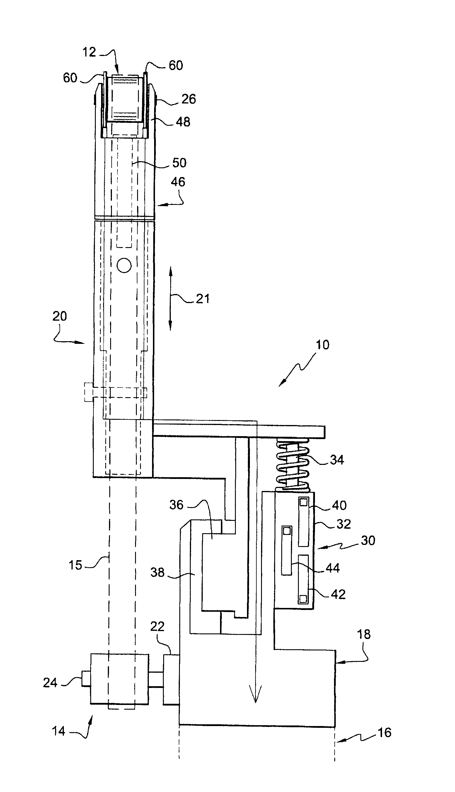
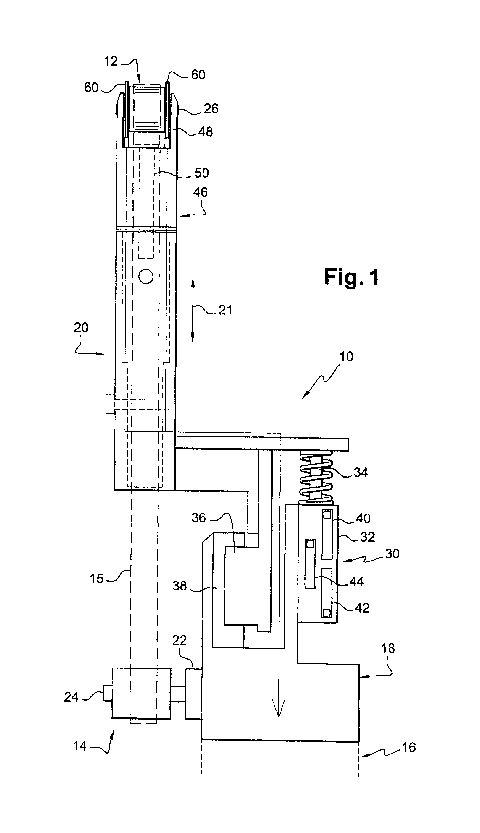
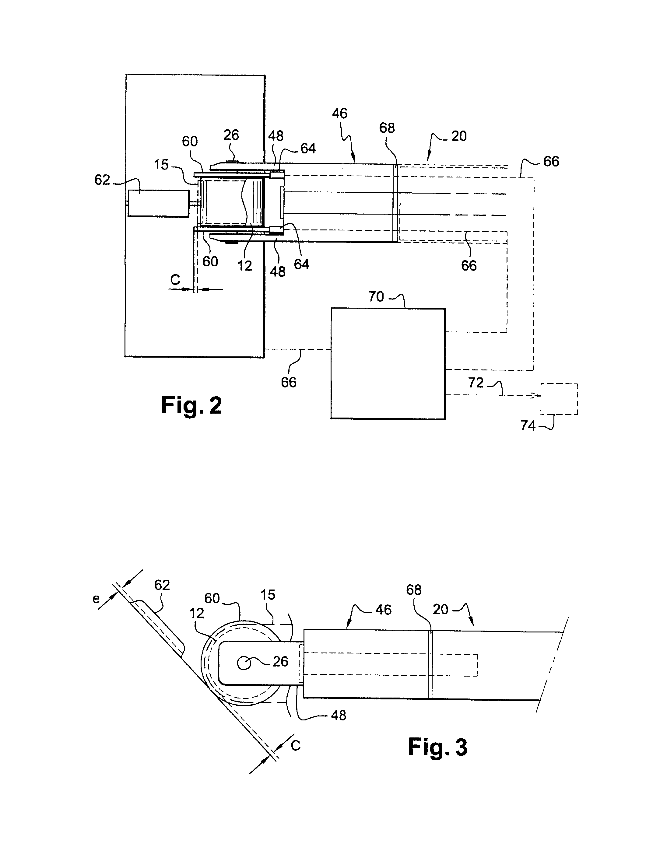
[0024]Referring initially to FIG. 1, this is a schematic view of a machine tool 10 according to the invention comprising at its front end a driven pulley 12 and at its rear end a driving pulley 14, these pulleys 12, 14 having parallel axes of rotation and being capable of driving and guiding an endless machining belt 15 such as an abrasive belt. The tool 10 is designed to be carried by a robot arm 16 to carry out operations of polishing, grinding, deburring, shaving, brushing, etc., on any workpiece such as for example an exhaust casing of a turbine engine.

[0025]As will be described in greater detail later, the tool 10 is moved by the robot arm 16 backwards or forwards in such a way that the machining belt 15, driven and guided by the pulleys 12, 14, is applied by the front pulley 12 to a surface of a workpiece to machine this surface by abrasion.

[0026]Here, the tool 10 is elongated in shape and comprises at the rear a base 18 mounted on one end of the robot arm 16, and at the front...


PUM


Abstract

A robotic machining tool, employing an endless machining belt (10), comprising a front pulley (12) and a rear pulley (14) for guiding a machining belt, the rear pulley being turned by drive means (22), and the front pulley being free to rotate about a spindle (26) and being flanked by two wheels (60) mounted idly on the spindle of the front pulley, these two wheels having an outside diameter greater than that of the front pulley in order to roll over a surface to be machined and in order to define a machining distance between the machining belt guided around the front pulley and the surface to be machined.

Description

[0001]This invention relates to a machine tool employing an endless machining belt designed to be mounted on a robot arm for the purpose of carrying out operations of polishing, grinding, deburring, shaving, brushing, etc., on any workpiece such as for example an exhaust casing of a turbine engine.BACKGROUND OF THE INVENTION[0002]The exhaust casing of a turbine engine is made up of several elements assembled together by weld beads which must be machined to produce a smooth profile along the weld bead and between the assembled elements.DESCRIPTION OF THE PRIOR ART[0003]The prior art includes a machine tool employing an endless abrasive belt guided around a driven pulley and a drive pulley whose axes of rotation are parallel, the driven pulley being mounted on the piston rod of a ram whose function is to separate the pulleys from each other and thus tension the abrasive belt between the pulleys.[0004]Where the workpieces are relatively complex, this tool must be manipulated and guided...

Claims


Application Information

Patent Timeline
IPC IPC(8): B24B23/06B24D99/00
CPCB24B9/00B24B49/10B24B21/18B24B21/16
Inventor L'HELGOUALC'H, CAROLEPEREIRA, PAUL ALEXANDRE
Owner SN DETUDE & DE CONSTR DE MOTEURS DAVIATION S N E C M A
Why Eureka
Try Eureka