Mobile device, moving system, moving method, and moving program

a technology of moving system and moving method, applied in the field of mobile devices, can solve problems such as difficulty in finding the location of an article over the whole working area

Inactive Publication Date: 2009-01-08
HITACHI LTD
View PDF29 Cites 126 Cited by
  • Summary
  • Abstract
  • Description
  • Claims
  • Application Information

AI Technical Summary

Benefits of technology

[0009]It is an object of the invention, being devised in light of these circumstances, to provide a technology by which the location where an article is placed is acquired and movement to that location is easily realized, even in cases where the article that was once placed in a location shielded from GPS signals is moved to a different place.

Problems solved by technology

Consequently, since it is difficult to estimate the robot location in places such as indoor areas which are shielded from GPS signals, it is difficult to find the location of an article over the whole of the working area.

Method used


Image

  • Mobile device, moving system, moving method, and moving program
  • Mobile device, moving system, moving method, and moving program
  • Mobile device, moving system, moving method, and moving program

Examples


first embodiment

[0024]First, a first embodiment will be described.

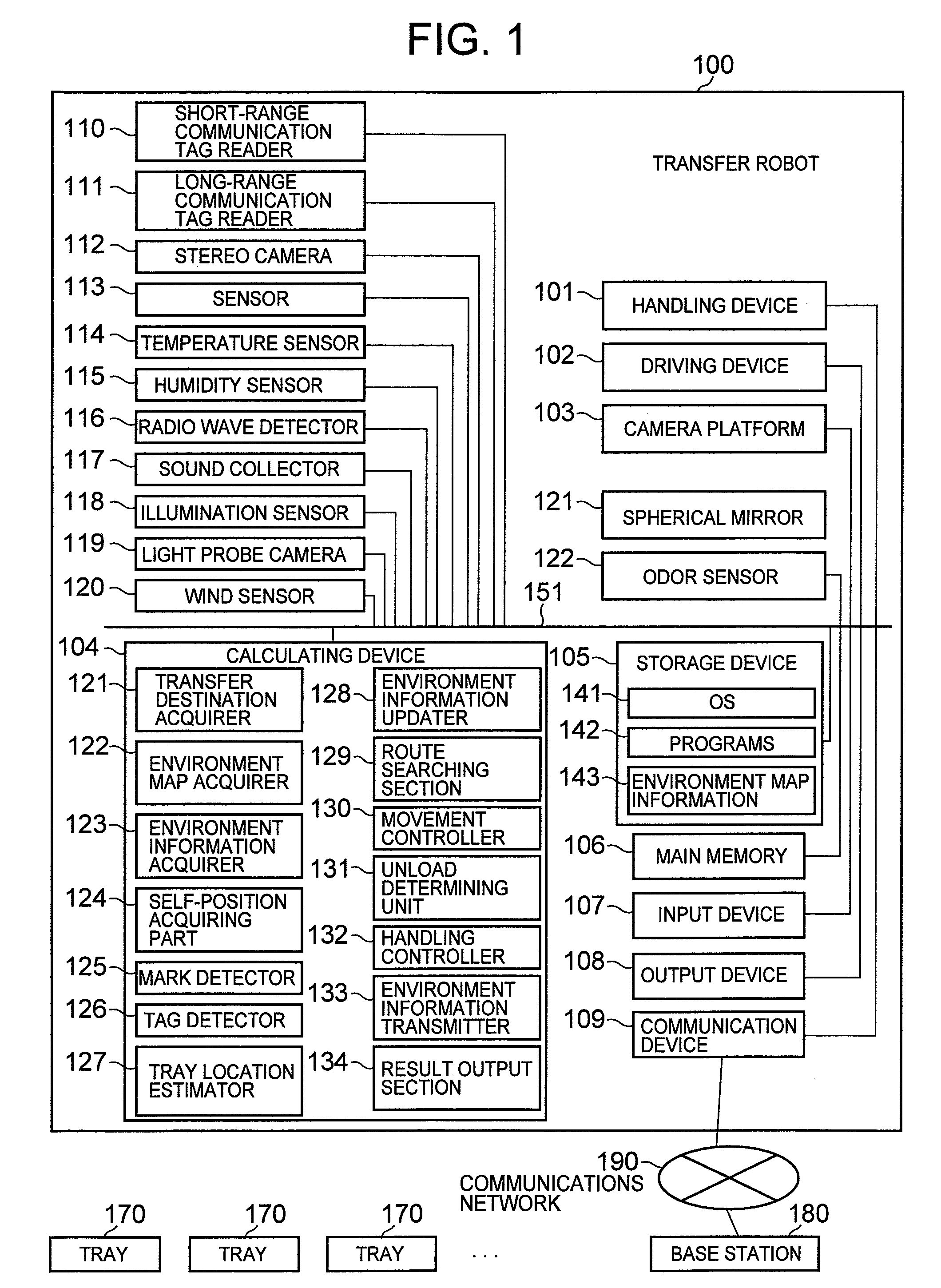
[0025]An example configuration of the first embodiment will be described with reference to FIG. 1.

[0026]The system of the present embodiment is comprised of a transfer robot 100, a plurality of trays 170, and a base station 180. The transfer robot 100 and the base station 180 are connected via a communications network 190.

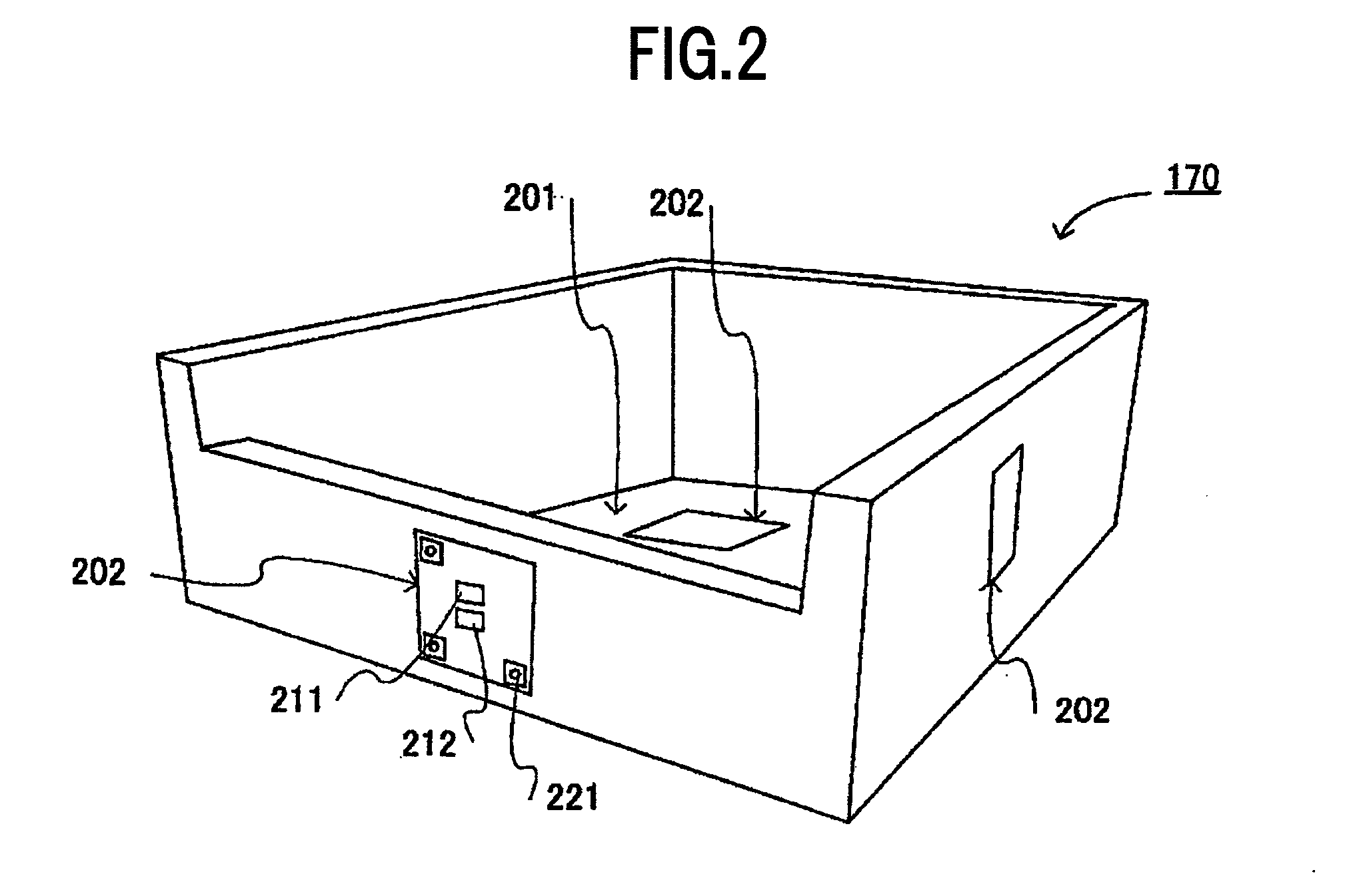
[0027]Each of the trays 170 is not fixed, but is movable. A mark, a short-range communication RFID tag, and a long-range communication RFID tag are attached to each of the trays 170. The details of these trays 170 will be described in a later section.

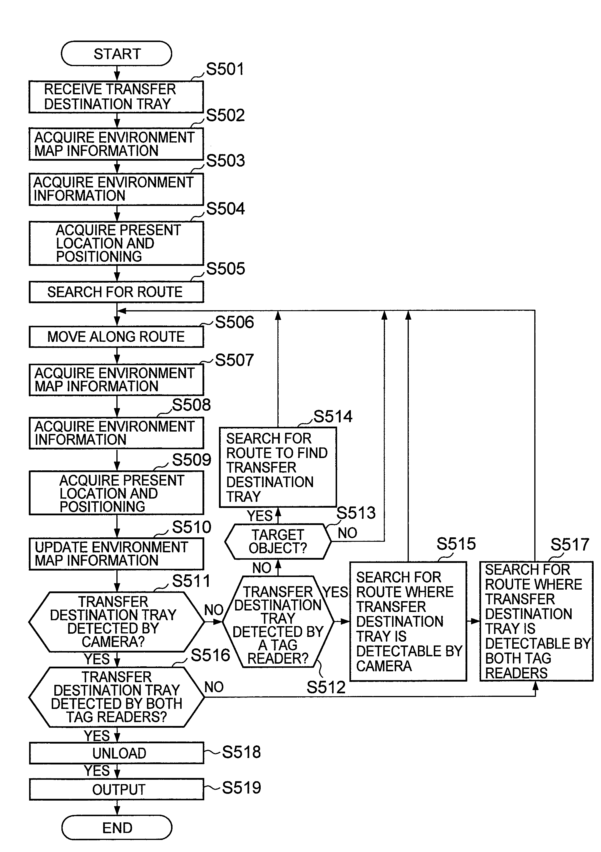
[0028]The transfer robot 100 acquires a location for a specified tray 170 from environment map information 143 sent from the base station 180, as well as from self-acquired information, and moves to that location. Details of the environment map information 143 will be described in a later section. At this point, the transfer robot 100, after having moved to the target t...

second embodiment

[0140]In the foregoing first embodiment, a single transfer robot 100 performed actions such as transferring objects. In a second embodiment to be hereinafter described, a plurality of transfer robots 100 transfer respective objects, and each transfer robot 100 mutually shares environment map information 143.

[0141]For portions of the second embodiment that are identical to those of the foregoing first embodiment, to be hereinafter described, identical reference numbers will be used in the description thereof.

[0142]First, a configuration example of the second embodiment will be described with reference to FIG. 11.

[0143]In FIG. 11, each of the plurality of transfer robots 100 is connected to a base station 180 via a communications network 190.

[0144]The base station 180 includes a storage device 1101. This storage device 1101 is an arbitrary storage medium such as a HDD or silicon disk. The storage device 1101 includes environment map information 143.

[0145]The example operation of each ...


PUM


Abstract

A technology is provided that easily acquires the location where an article is placed and then moves to that location, even in cases where the article was originally placed in a location shielded from GPS radio wave, and subsequently moved to another location. Marks and RFID tags are affixed to a movable tray. A transfer robot includes a camera, a reader, and a sensor. The transfer robot detects the tray location from the location of a region in an image photographed by the camera that matches mark information. Furthermore, the reader in the transfer robot detects the tray location from the intensity of a radio wave whose information, when read, matches an ID retained in the RFID tag. The transfer robot moves with the camera and the reader, detecting the tray that is the target destination.

Description

BACKGROUND OF THE INVENTION[0001]1. Field of the Invention[0002]The present invention relates to mobile devices.[0003]2. Description of the Related Art[0004]RFID (Radio Frequency Identification) technology may conceivably be applied to article management. For example, in inventory management, by affixing an RFID tag (hereinafter, tag) to each article, and by reading an ID within that tag, it is possible to acquire information on the type and quantity of that article. By conducting this process when loading or unloading from a warehouse or other repository, inventory management becomes easier.[0005]In addition, a technology that searches for the location of an article stored in a warehouse or other repository, and to which an RFID tag is affixed, is described in Patent Reference 1. Patent Reference 1 describes a technology whereby a robot acquires the location of an RFID tag.[0006]Patent Reference 1: Japanese Patent Laid-Open Publication No. 2005-320074SUMMARY OF THE INVENTION[0007]I...

Claims


Application Information

Patent Timeline
Patent Type & Authority Applications(United States)
IPC IPC(8): G05D1/00
CPCG05D1/024G05D1/0242G05D1/0251G05D2201/0216G05D1/0261G05D1/0274G05D1/0255
Inventor MATSUMOTO, KOSEIMORIYA, TOSHIO
Owner HITACHI LTD
Why Eureka
Try Eureka