
Device and Method of Measuring Depth and Azimuth

a technology of depth and azimuth, which is applied in the direction of instruments, surveying, and wellbore/well accessories, etc., can solve the problems of inability to estimate the precise depth of the downhole assembly at a particular instant, the lack of synchronization between the uphole and the downhole clock, and the movement of the downhole assembly within the wellbore. to achieve the effect of improving the analysis and interpretation of data

Active Publication Date: 2009-01-08
SCHLUMBERGER TECH CORP
View PDF1 Cites 9 Cited by
  • Summary
  • Abstract
  • Description
  • Claims
  • Application Information

AI Technical Summary

Benefits of technology

The invention proposes a method and device for measuring the depth and azimuth of logging data in a wellbore. The method involves acquiring and storing two frames of logging data, where the second frame overlaps the first frame. The method calculates the relative change in the depth and azimuth of the logging data by comparing the two frames. This allows for accurate estimation of the relative depth and azimuth of the downhole assembly moving in the wellbore. The invention can be used in various applications such as drilling and wellbore construction.

Problems solved by technology

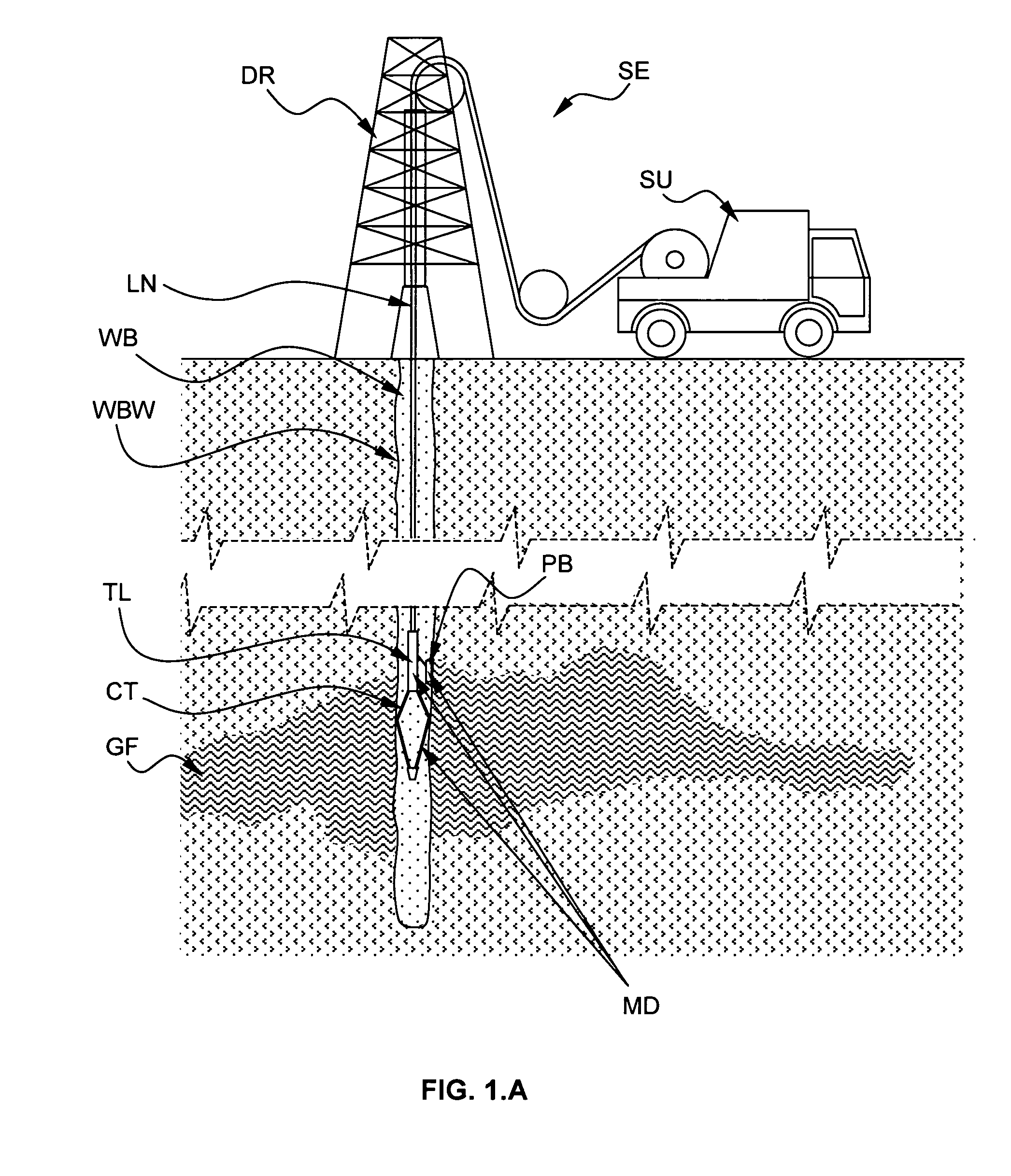
During the deployment and operation of the logging tool and drilling assembly, these downhole assemblies may move erratically within the well bore (e.g. bouncing effects, sticking and releasing effects, friction, compression or tension of the pipe or cable).
Thus, it is often difficult to estimate at a particular instant the precise depth of the downhole assembly.
In addition, in logging while drilling application, an additional error is introduced by the lack of synchronization between the uphole and downhole clocks.
As a consequence, log produced by the sensors of the downhole assembly will be incorrect as a result of the errors made when correlating measurements performed by the sensors of the downhole assembly with depth measurements made at the surface.
Further, the aforementioned estimated depths will be insufficiently precise for high resolution measurements such as images.

Method used


Image

  • Device and Method of Measuring Depth and Azimuth
  • Device and Method of Measuring Depth and Azimuth
  • Device and Method of Measuring Depth and Azimuth

Examples


second embodiment

[0064]The measuring device according to a first and second embodiment of the invention that will be described in relation with FIGS. 2.A and 4.A, respectively, may be fitted in any type of downhole assembly (logging tool, drilling assembly, or any other tool conveyed in any other fashion). The downhole assembly may be rotated clockwise or counterclockwise, move up or down into the wellbore resulting in a positive or negative variation of the depth and / or azimuth of the downhole assembly into the wellbore.

first embodiment

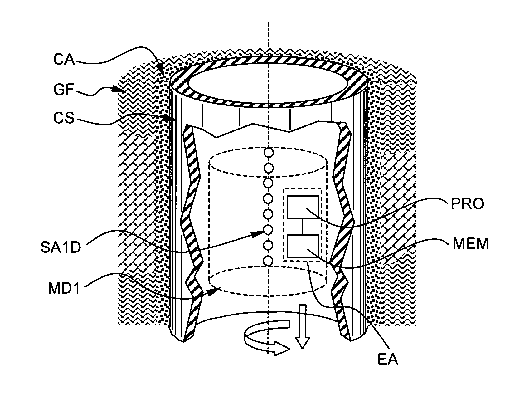
[0065]FIG. 2.A schematically shows a cross-section into a portion of a cased wellbore and illustrates the depth and / or azimuth measuring device MD1 according to the invention.

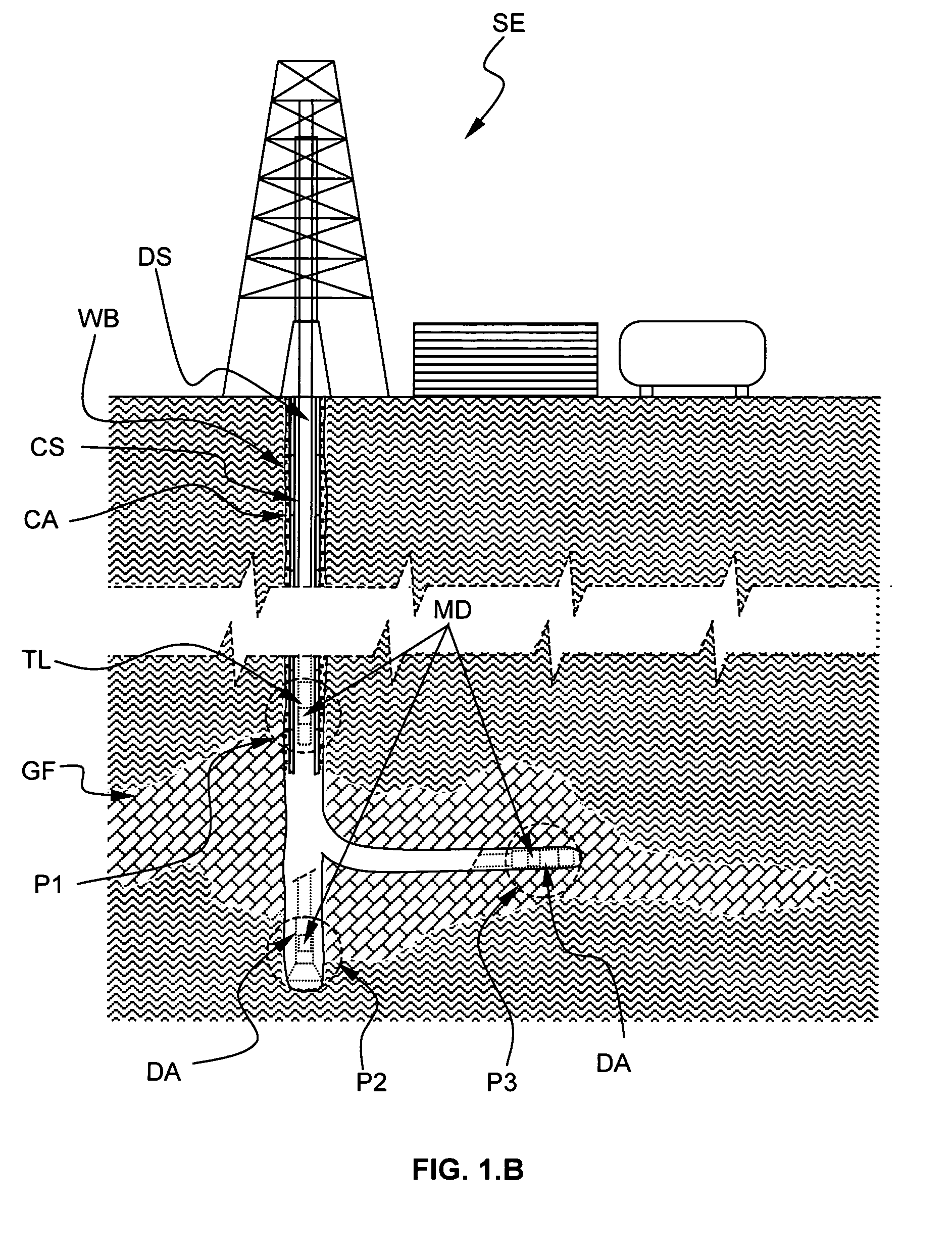
[0066]The depth and / or azimuth measuring device MD1 is coupled to a 1D sensor array SA1D. In the example of FIG. 2.A, the 1D sensor array comprises 8 sensors and is positioned substantially vertically, thus enabling measuring depth. Alternatively, it will be apparent that the 1D sensor array may also be positioned substantially horizontally (not shown), thus enabling measuring azimuth. The 1D sensor array may be a specific sensor which function is only to be used in the determination of the depth and / or azimuth. Alternatively, the 1D sensor array may be part of the logging tool TL or the drilling assembly DA (see FIGS. 1.A and 1.B) which function is to determine the physical property of the zone surrounding the wellbore, e.g. the geological formation GF, the casing CS or the cemented casing. In this example, th...


PUM


Abstract

A method of measuring depth and / or azimuth of logging data, the logging data being related to at least one property of a zone GF, CS, CA surrounding a wellbore and being measured by at least a sensor array SA1D, SA2D, the method comprising the steps of:acquiring and storing a first logging data frame F11, F21 corresponding to a first position of the sensor array,acquiring and storing a second logging data frame F12, F22 corresponding to a second position of the sensor array, the first and second position are such that the second logging data frame F12, F22 overlaps at least partially the first logging data frame F11, F21, comparing the first F11, F21 and second F12, F22 logging data frame, andcalculating a relative change in the depth ΔDP and / or azimuth ΔAZ of logging data measured by the sensor array SA1D, SA2D between the first F11, F21 and second F12, F22 logging data frame.

Description

FIELD OF THE INVENTION[0001]The invention relates to a method of measuring depth and / or azimuth of logging data related to a physical property of a geological formation surrounding a wellbore measured by at least a sensor array, and a device for measuring depth and azimuth according to the same method.[0002]Other aspects of the invention relate to a logging tool and a drilling assembly.[0003]A particular application of the method and the logging tool according to the invention relates to the oilfield services industry.BACKGROUND OF THE INVENTION[0004]Many techniques are known to measure the depth as well as the azimuth of downhole assemblies deployed within a wellbore. The downhole assemblies may be a logging tool (used in wireline application) or a drilling assembly (used in drilling and logging while drilling applications) which comprise a plurality of sensors for measuring properties of the geological formation surrounding the wellbore.[0005]Typically, in wireline application, th...

Claims


Application Information

Patent Timeline
Patent Type & Authority Applications(United States)
IPC IPC(8): G01V9/00E21B47/04
CPCG01V11/002E21B47/04
Inventor VAN OS, ROELDION, DOMINIQUECHEUNG, PHILIP
Owner SCHLUMBERGER TECH CORP
Learn More