Transaction Method for Managing the Storing of Persistent Data in a Transaction Stack

a transaction stack and persistent data technology, applied in the direction of multi-programming arrangements, instruments, electric digital data processing, etc., can solve the problems of not considering a transaction method for storing persistent data, affecting the functioning of the electronic device, and the value of persistent data is left in an inconsistent sta

Active Publication Date: 2009-01-08
STMICROELECTRONICS INT NV
View PDF2 Cites 225 Cited by
  • Summary
  • Abstract
  • Description
  • Claims
  • Application Information

AI Technical Summary

Benefits of technology

[0035]FIG. 3c schematically shows in more de

Problems solved by technology

If an accidental electrical deactivation occurs during an application execution, specifically during an updating operation of persistent data, it is possible that the value of persistent data is left in an inconsistent state.
This could compromise, completely or partially, the functioning of the electronic device in the successive power-on sessions.
They do not consider a transaction method for storing persistent data in case of other unexpected events not determined by a power off.
This limitation has an impact on the implementation of the transaction method for driving the transaction stack, as any “Secure Update” involving a number of secure writing operations has the side effect of a further writing in the transaction stack.
In other words, different portions or bytes of the transaction stack could not be used uniformly.
Even if the device is guaranteed for 100,000 writing operations on each single byte of the non-volatile memory, the electronic device cannot perform more than 100,000 “Secure updating” even on different memory bytes.
This is because in an opposite case, the bytes already stressed in the transaction stack could be damaged.
More pa

Method used


Image

  • Transaction Method for Managing the Storing of Persistent Data in a Transaction Stack
  • Transaction Method for Managing the Storing of Persistent Data in a Transaction Stack
  • Transaction Method for Managing the Storing of Persistent Data in a Transaction Stack

Examples


Embodiment Construction

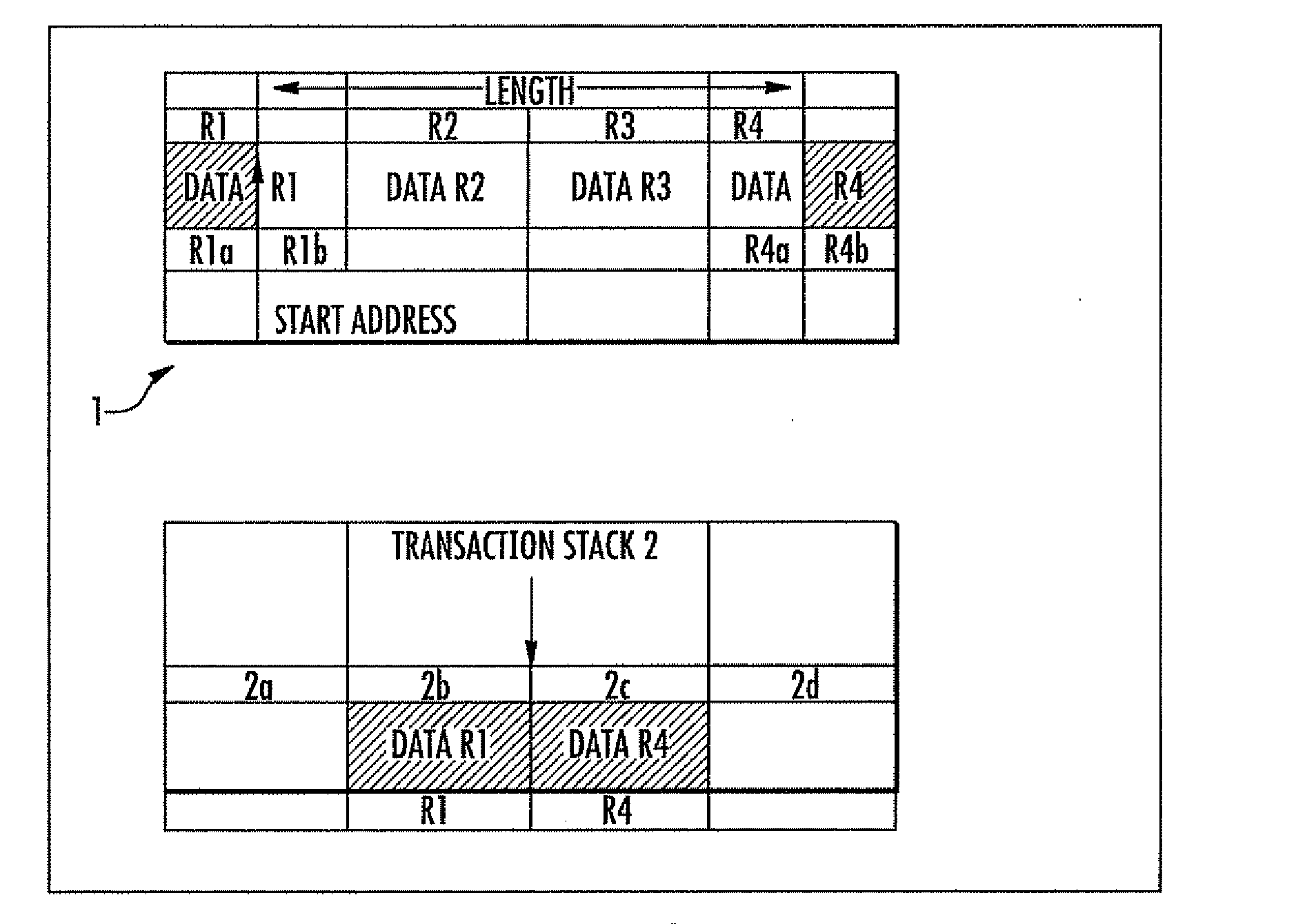
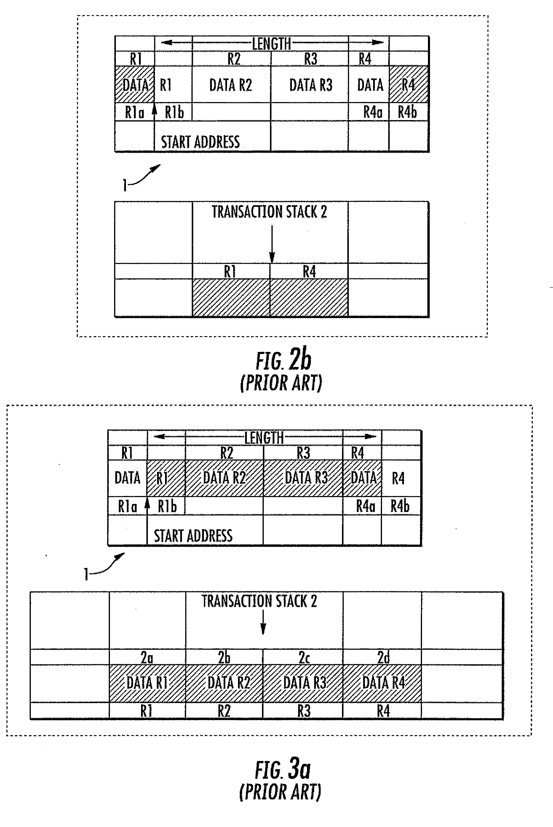
[0038]With more specific reference to FIG. 3a, a non-volatile memory device 1 comprises a plurality of memory portions R1-R4 that are provided for respectively storing persistent data data-R1 . . . data-R4. A transaction stack 2 comprises a plurality of transaction entries 2a-2d for storing the persistent data data-R1 . . . data-R4 during an update phase.

[0039]More particularly, as shown in more detail in FIG. 3a, the memory portion R1 of the non-volatile memory 1 comprises two sub-regions R1a and R1b, respectively including a first and a second group of persistent data data-R1a and data-R1b. Also, the memory portion R4 comprises two corresponding sub-regions R4a and R4b including a first and a second group of persistent data data-R4a, data-R4b.

[0040]An update operation may affect only a group of the persistent data, for example identified by memory sub-region data-R1b, memory regions data-R2, data-R3, and memory sub-region data-R4a. During the execution of such an update operation...


PUM


Abstract

A transaction method manages the storing of persistent data to be stored in at least one memory region of a non-volatile memory device before the execution of update operations that involve portions of the persistent data. Values of the persistent data are stored in a transaction stack that includes a plurality of transaction entries before the beginning of the update operations so that the memory regions involved in such an update are restored in a consistent state if an unexpected event occurs. A push extreme instruction reads from the memory cells a remaining portion of the persistent data that is not involved in the update operation, and stores the remaining portion in a subset of the transaction entries. The push extreme instruction is executed instead of a push instruction when the restoring of the portion of persistent data is not required after the unexpected event. The restoring corresponds to the values that the persistent data had before the beginning of the update operations.

Description

FIELD OF THE INVENTION[0001]The present invention relates to the storing of persistent data in a non-volatile memory device. More particularly, the present invention relates to managing the storing of the persistent data in a transaction stack before the execution of at least one update operation that involves at least a portion of the persistent data.BACKGROUND OF THE INVENTION [0002]A non-volatile memory, such as a Flash memory or an EEPROM memory, is used in an electronic device to store non-volatile data. Such non-volatile data is also indicated as persistent data because its content may be variable during the programming phases of the electronic memory device, but its value must be preserved during the power off.[0003]More particularly, the non-volatile memory ensures that the value of persistent data is not lost after a regular switch-off of the electronic device, i.e., when the electrical deactivation occurs in an idle state of the device. This is the typical case when the de...

Claims


Application Information

Patent Timeline
IPC IPC(8): G06F12/02G06F12/00G06F13/00G06F12/16
CPCG06F11/1441G06F11/1474G06F11/1469G06F9/466G06F2201/82
Inventor SEPE, PAOLODI COSMO, LUCAMUSELLA, ENRICO
Owner STMICROELECTRONICS INT NV
Why Eureka
Try Eureka