Method and device for detecting, determining and documenting damage, especially deformations in lacquered surfaces caused by sudden events

a technology of sudden events and damage, applied in the field of recording, measuring and documenting damages, can solve the problems of lowering the sale or re-sale value of passenger vehicles, vehicles, especially new or unused passenger vehicles, sometimes suffer significant damage from depressions and/or dents on their roofs, hoods, etc., and achieves high scanning speed, high resolution, and precise images.

Inactive Publication Date: 2007-06-28
PRISTNER ERWIN
View PDF10 Cites 36 Cited by
  • Summary
  • Abstract
  • Description
  • Claims
  • Application Information

AI Technical Summary

Benefits of technology

[0009] The method according to the invention makes it possible to objectively measure, record, and document, for all parties involved, damages, such as small surface-area depressions to painted body parts, which damages were caused by hail storms. Furthermore, appropriate repair and maintenance of the damaged vehicle can be demonstrated with the inventive solution. Of particular advantage is the mobility attained with the inventive solution, by virtue of which, it is possible to undertake a cause-related damage assessment within a short period of time after a hailstorm strikes.
[0010] By using a focused light beam, for example, a laser beam with a small spot diameter, a precise image of the damaged surface with very high resolution can be attained. The inventive method furtherm...

Problems solved by technology

Frequently, especially in the summer months, it is not possible to shelter vehicles in sufficient time when there is a hailstorm.
These vehicles, especially new or unused passenger vehicles, delivery trucks, or the like, sometimes suffer significant damages from depressions and/or dents on their roofs, hoods, trunk lids, fenders, doors, spoilers, sides, and/or roof rails.
Small, barely visible dents particularly lower the sale or re-sale value of a passenger vehicle damaged in this manner.
However, small and barely visible depressions frequently lead to frustrating and acri...

Method used


Image

  • Method and device for detecting, determining and documenting damage, especially deformations in lacquered surfaces caused by sudden events
  • Method and device for detecting, determining and documenting damage, especially deformations in lacquered surfaces caused by sudden events
  • Method and device for detecting, determining and documenting damage, especially deformations in lacquered surfaces caused by sudden events

Examples


example 1

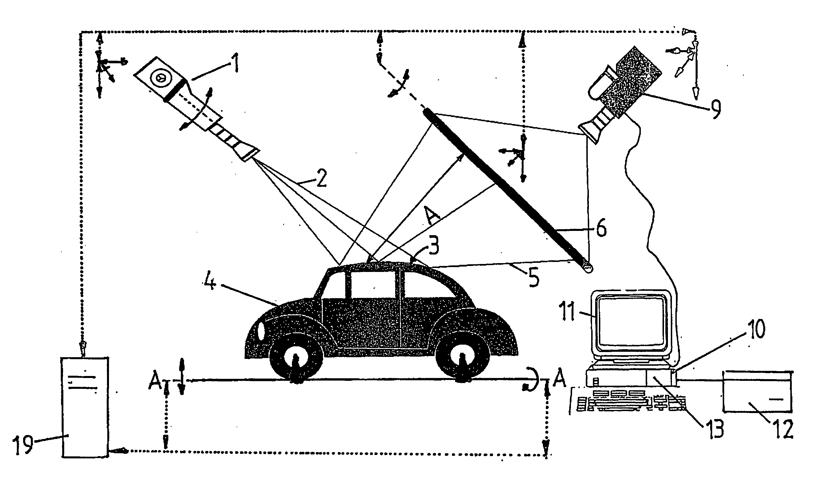
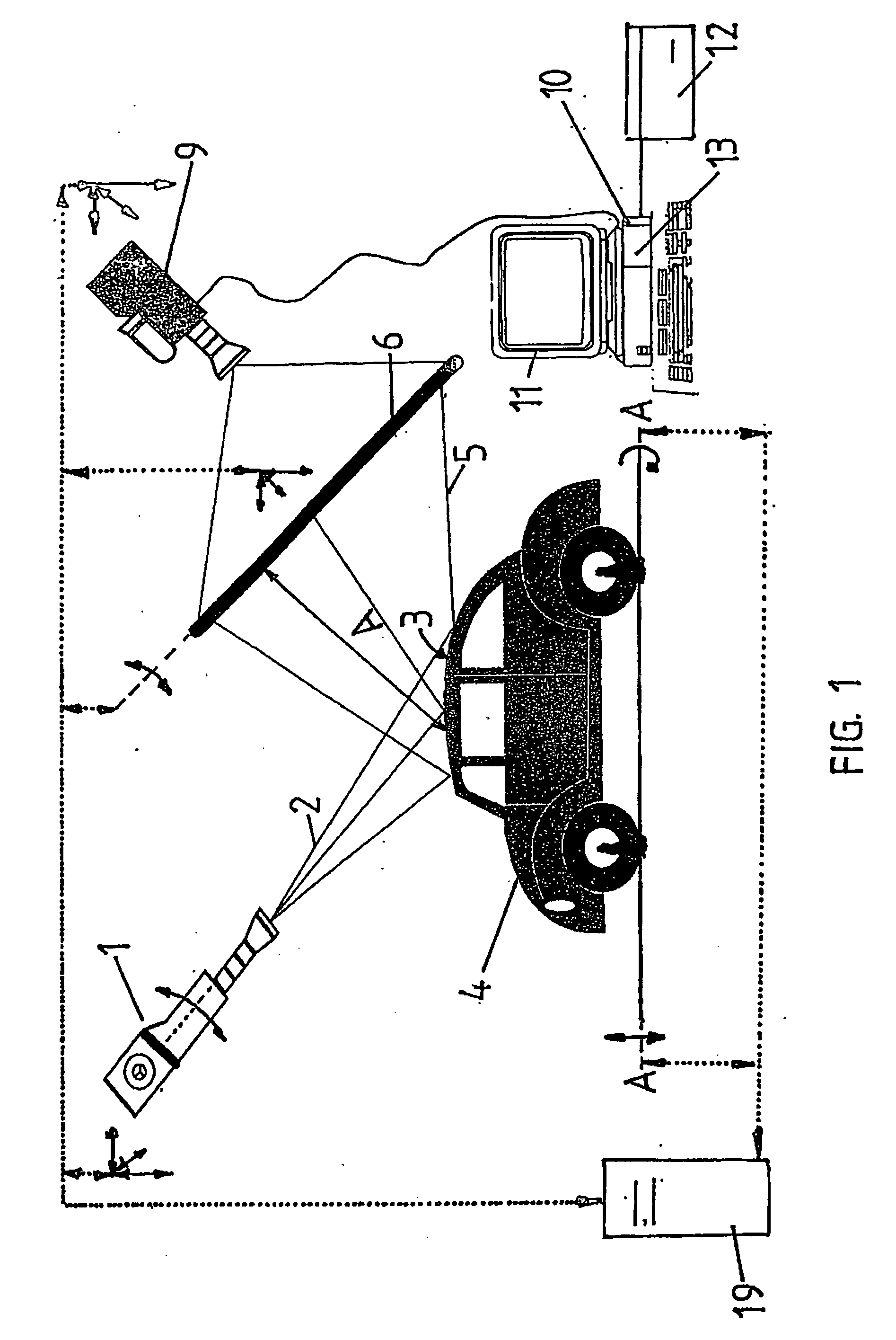
[0021]FIG. 3 illustrates the design of the inventive method within a container-like support frame 14 in which the vehicle 4 to be tested is situated.

[0022] This support frame 14 largely comprises the upper lateral braces a and b, the lower lateral braces c and d, the front end braces e, f, g, and h, and the rear end braces i, j, k, and l, assembled. One of each type of side brace, a vertical and a horizontal side brace, are joined to one another in a surface fit using corner fittings. The side walls are pivotably hinged at the lower side braces c and d and the lower side braces f and j so that at the set-up location the support frame 14 is freely accessible on all sides by opening the side walls 15 and end wall 21.

[0023] Mounted along the upper side braces a and b, the front upper horizontal and vertical end braces e, g, and h, and the rear horizontal and vertical end braces i, k, and l, are guide rails 16 that guide the surface scanner 1 and the screen 6. The surface scanner 1 is...

example 2

[0029] The structure of the inventive apparatus in Example 2 is largely the same as that in Example 1. The difference is that the vehicle 4 is not lifted and does not make a rotational or pivoting movement. The body surface is scanned in that, for an immobile or moved vehicle, only the surface scanner 1 performs a displacement movement in the horizontal and vertical direction, and the screen 6 is brought into the corresponding intercepting position for the reflected laser light beams 2.

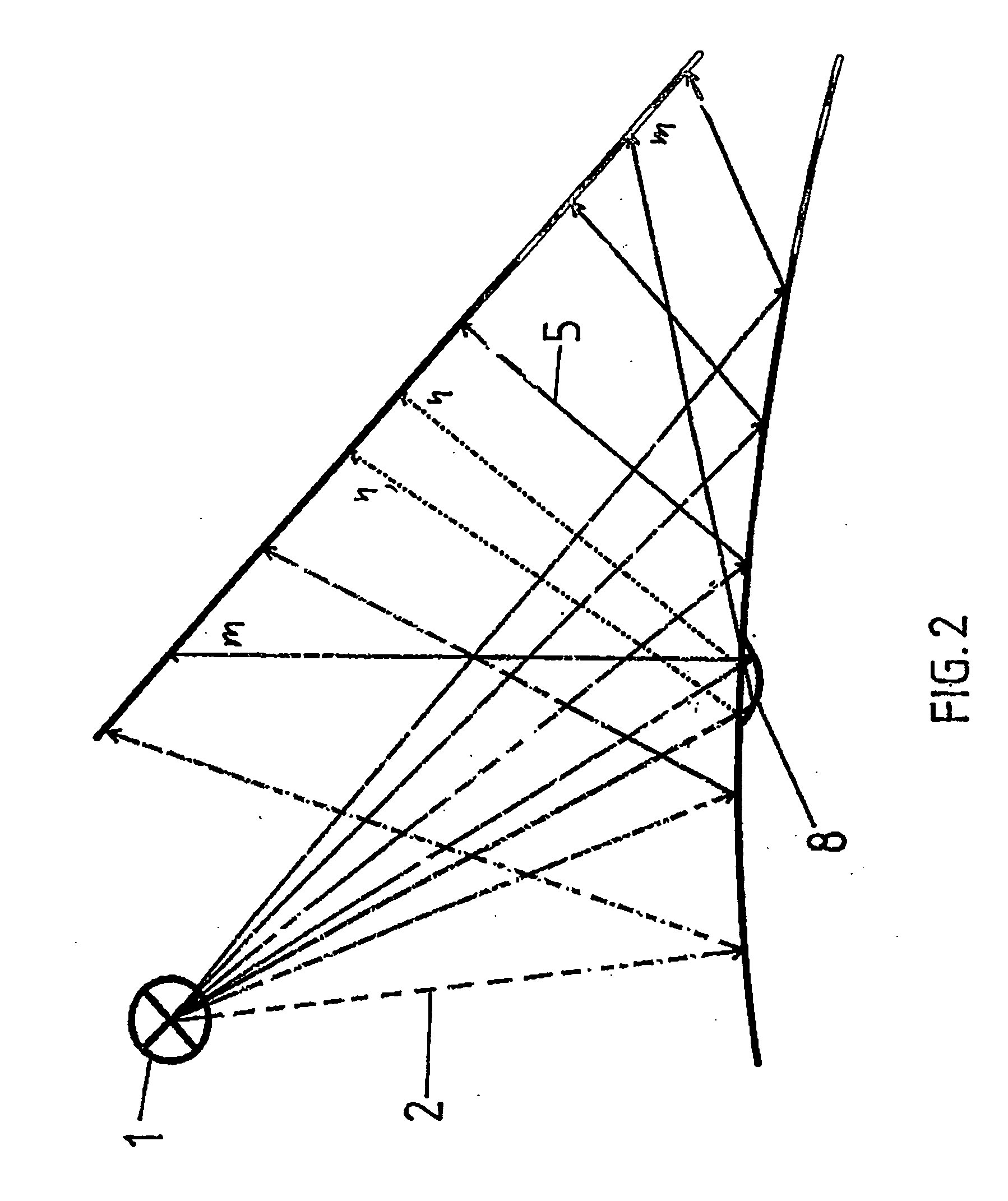
Key to reference numbers usedLight source, surface scanner 1Laser light beam 2Surface of body 3Vehicle 4Reflected beams 5Screen 6Line 7Depression 8Digital camera 9Evaluation and signal processing10unitMonitor11Printer12Microprocessor13Support frame14Side wall15Guide rails16Measurement table17Fasteners18Processor unit19Communication and operator20space for 14End wall21Distance from surface to screenALongitudinal axis of vehicle 4A—AUpper lateral braces for 14a, bLower lateral braces for 14c, dFront s...


PUM


Abstract

A method and a device for detecting, determining and documenting damage to painted surfaces, especially parts of the bodywork of vehicles, utilizes light from at least one heavily focusing light source directed to a test surface in a grid-type or raster-type manner to produce a surface image on a screen with the light reflected on the test surface of the vehicle, the image being detected by a capturing, evaluating and signal processing device. The surface damage therein is then determined according to a specific evaluation algorithm and outputted for objective documentation of the damage. Results are achieved by coordinated, controlled displacement and/or pivoting between the light source and screen and by means of a rotational and/or displacement and or pivoting movement of the vehicle, which is controlled in accordance with the displacement and/or pivoting, around or along the longitudinal and/or vertical axis thereof inside a load-bearing structure, wherein the respective surface area to be sensed is brought towards the light source in the reflection position and the screen and the capturing device are brought towards the reflected light in an imaging position and the movements of the light source, screen, capturing device and vehicle are controlled by a processor unit.

Description

BACKGROUND OF THE INVENTION [0001] The invention relates to a method for recording, measuring, and documenting damages, in particular deformations such as depressions or the like, that are caused by sudden events, for instance hailstorms, to painted surfaces, in particular body parts of vehicles, in which the surface to be examined on the vehicle is scanned with light from at least one highly focusing light source in a lattice- or grid-pattern and with the light reflected on the surface, a surface image is produced on a screen, which is recorded by an evaluation and signal processing device and, the surface damages are thereby determined using a certain evaluation algorithm and are output for objectively documenting the damages. [0002] The invention furthermore relates to an apparatus for recording, measuring, and documenting damages, in particular deformations such as depressions or the like that are caused by sudden events, for instance hailstorms, to painted surfaces, in particul...

Claims


Application Information

Patent Timeline
IPC IPC(8): G01B11/24B60S5/00G01B11/00G01B11/30G01B21/20G01B21/30G01N21/88
CPCB60S5/00G01B11/306G01N21/8806
Inventor PRISTNER, ERWIN
Owner PRISTNER ERWIN
Why Eureka
Try Eureka