Remote monitoring and diagnostic sytem

a technology of remote monitoring and diagnostic software, applied in the field of remote monitoring and diagnostic system, can solve the problems of difficult to update the optimum difficult to previously verify the monitoring and diagnostic software, and difficult to adapt to update the triggers of various pieces of monitoring and diagnostic software. to achieve the effect of efficient updating of monitoring and diagnostic softwar

Inactive Publication Date: 2009-01-08
KK TOSHIBA
View PDF1 Cites 34 Cited by
  • Summary
  • Abstract
  • Description
  • Claims
  • Application Information

AI Technical Summary

Benefits of technology

[0022]An object of the invention is to provide a remote monitoring and diagnostic system which can previously verify the monitoring and diagnostic software, adapt to various update triggers, and efficiently update the monitoring and diagnostic software even if many monitoring objects are connected.

Problems solved by technology

However, in the case where many monitoring objects exist, it is extremely difficult that the optimum monitoring and diagnostic software is updated as an entire the system including the many monitoring objects.
(1) It is difficult to previously verify the monitoring and diagnostic software.
(2) It is difficult to adapt to update triggers of various pieces of monitoring and diagnostic software.

Method used


Image

  • Remote monitoring and diagnostic sytem
  • Remote monitoring and diagnostic sytem
  • Remote monitoring and diagnostic sytem

Examples


first embodiment

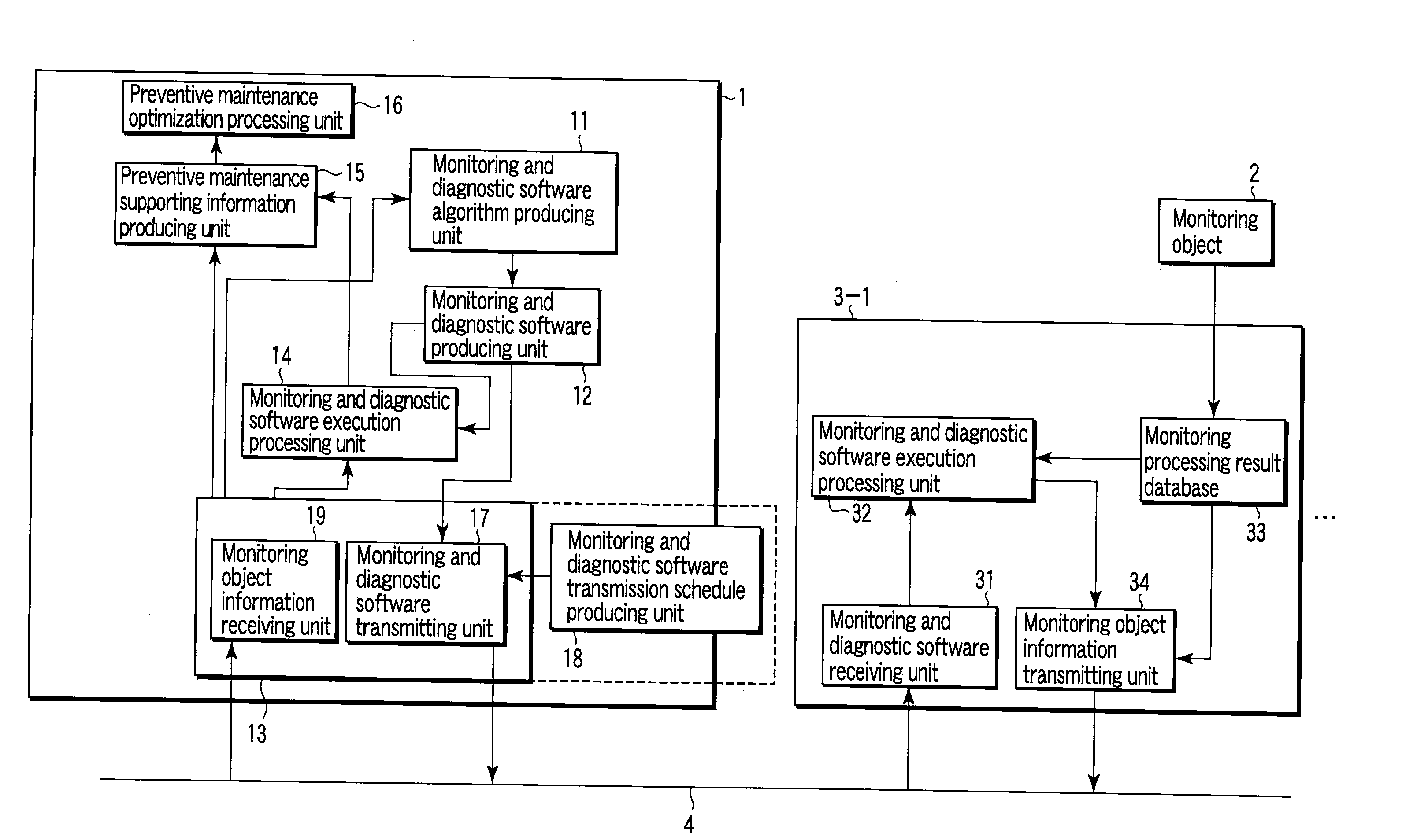
[0046]FIG. 1 is a block diagram showing a remote monitoring and diagnostic system according to a first embodiment of the invention.

[0047]In the remote monitoring and diagnostic system, a center-side processing system 1 which acts as a center and monitoring object-side monitoring processing systems 3-1, . . . which monitor and diagnose monitoring objects 2 respectively are connected through a communication network 4.

[0048]The center-side processing system 1 includes a monitoring and diagnostic software algorithm producing unit 11, a monitoring and diagnostic software producing unit 12, a platform 13 which constitute a base of delivery and receipt of software and data, a monitoring and diagnostic software execution processing unit 14, a preventive maintenance supporting information producing unit 15, and a preventive maintenance optimization processing unit 16.

[0049]The monitoring and diagnostic software algorithm producing unit 11 produces algorithms of source codes which define moni...

second embodiment

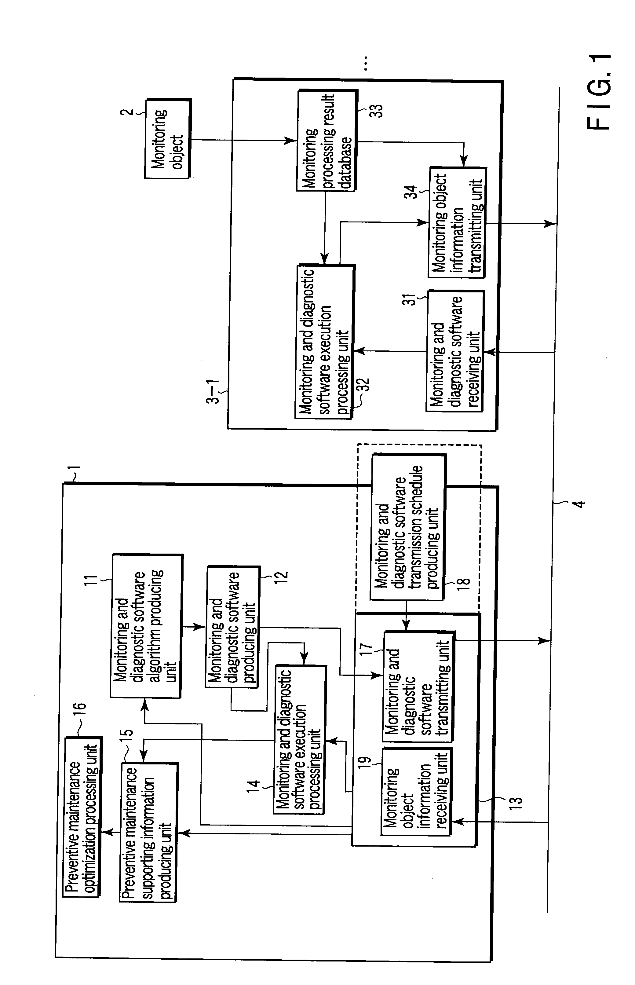
[0107]FIG. 2 is a block diagram showing a remote monitoring and diagnostic system according to a second embodiment of the invention.

[0108]The remote monitoring and diagnostic system of the second embodiment is similar to the remote monitoring and diagnostic system of the first embodiment in that the center-side processing system 1, which acts as the center, and the monitoring object-side monitoring processing systems 3-1, . . . , which monitor and diagnose the monitoring objects 2, are respectively connected through the communication network 4.

[0109]The remote monitoring and diagnostic system of the second embodiment differs particularly from the remote monitoring and diagnostic system of the first embodiment in a platform 13a of the center-side processing system 1. Accordingly, because other configurations except for the platform 13a are similar to those of the first embodiment, the description is omitted.

[0110]As described above, a software version management unit 20 and a databas...

third embodiment

[0122]FIG. 3 is a block diagram showing a remote monitoring and diagnostic system according to a third embodiment of the invention.

[0123]In the remote monitoring and diagnostic system of the third embodiment, the center-side processing system 1 which acts as the center and the monitoring object-side monitoring processing systems 3-1, . . . which monitor and diagnose the monitoring objects 2 are respectively connected through the communication network 4.

[0124]The center-side processing system 1 has a configuration in which a monitoring and diagnostic software verification processing unit 22 is newly added to the monitoring and diagnostic software producing unit 12 in addition to all the components 11 to 21 shown in FIG. 2. Accordingly, because the components 11 to 21 of the center-side processing system 1 shown in FIG. 3 are similar to those of the first and second embodiments, the description is omitted.

[0125]On the other hand, in each of the monitoring object-side monitoring proces...


PUM


Abstract

A center-side processing system and monitoring processing systems of monitoring objects are connected through a network. The center-side processing system includes a module for producing monitoring and diagnostic algorithms of the monitoring objects, software producing module for producing monitoring and diagnostic software from the monitoring and diagnostic algorithm, a module for producing a transmission schedule of the monitoring and diagnostic software, transmitting module for transmitting software according to the transmission schedule, a module for correcting and changing the monitoring and diagnostic software from data received from the monitoring processing system, and verification module for performing verification before the transmission of the monitoring and diagnostic software. Each of the monitoring processing systems includes a module for receiving the monitoring and diagnostic software, execution processing module for executing the monitoring and diagnostic software, a module for automatically verifying the monitoring and diagnostic software, and transmitting module.

Description

CROSS REFERENCE TO RELATED APPLICATIONS[0001]This is a Continuation Application of PCT Application No. PCT / JP2008 / 050290, filed Jan. 11, 2008, which was published under PCT Article 21(2) in Japanese.[0002]This application is based upon and claims the benefit of priority from prior Japanese Patent Application No. 2007-007293, filed Jan. 16, 2007, the entire contents of which are incorporated herein by reference.BACKGROUND OF THE INVENTION[0003]1. Field of the Invention[0004]The present invention relates to a remote monitoring and diagnostic system which monitors and diagnoses many monitoring objects.[0005]2. Description of the Related Art[0006]Conventionally, for the remote monitoring and diagnostic system which monitors and diagnoses the remote monitoring object, there have been developed and proposed various techniques in which various remote monitoring methods are adopted. Some conventional remote monitoring and diagnostic systems will be described below.[0007]One of the remote mo...

Claims


Application Information

Patent Timeline
Patent Type & Authority Applications(United States)
IPC IPC(8): G06F9/44G05B23/02G06Q50/00G06Q50/06G06Q50/10
CPCG05B23/0213H04L12/6418G05B2219/31457
Inventor OOBA, YOSHIKAZUSEKI, YOSHIROIDEMORI, KIMITOKOBAYASHI, SHUICHIROOOHASHI, HIROYUKISUMI, KATSUHIRO
Owner KK TOSHIBA
Why Eureka
Try Eureka