Active sterilization zone for container filling

a technology of container and active sterilization zone, which is applied in the direction of liquid handling, application, packaging goods type, etc., can solve the problems of cumbersome operation of aseptic filling lines, time-consuming, and limiting production capacity,

Inactive Publication Date: 2009-01-15
STOKLEY VAN CAMP INC
View PDF98 Cites 24 Cited by
  • Summary
  • Abstract
  • Description
  • Claims
  • Application Information

AI Technical Summary

Benefits of technology

[0010]According to one exemplary embodiment, the containers are directed via an in-line conveyor assembly through the first module and the second module. Once the containers are de-palletized and directed into the first module via the conveyor assembly, the containers pass through a waterless rinsing station and then are directed to a container sterilization unit having a high-powered electron beam emitter wherein the containers are initially sterilized. The containers are then conveyed to the second module having a filler assembly wherein the containers are filled with a beverage or product under aseptic conditions. The containers are then transferred to the capper assembly. A second sterilization unit is operably associated with the filler assembly and capper assembly in the second module. In one exemplary embodiment, the sterilization unit has low-powered e-beam emitters that provide a sterile environment for the filling and capping of products such as beverages, liquids, or foods, etc. The sterilization unit and other associated structures and systems provide the active sterilization zone in the CHE in which the containers travel. The sterilization technique disclosed herein can be used to sterilize any type of container whether the container is adapted to receive, for example, filtered, preserved, or pasteurized product. The product is maintained at a generally ambient temperature. The sterile filled and capped containers are then directed for further packaging.
[0011]In an exemplary embodiment a method for filling containers while maintaining a sterile environment is disclosed. The method has the steps of substantially sterilizing a gripper adapted to receive a container and a filler valve adapted to fill a container, receiving an unfilled container with the gripper, filling the container with a filler valve, and transferring the filled container off of the gripper to a capping operation. The first gripper can be sterilized by directing first and second e-beam emitters upwards at an area through which the gripper passes proximate to points on the gripper which contact the container during the filling operation.
[0012]In another exemplary embodiment an apparatus for filling containers while maintaining a sterile environment is disclosed. The apparatus has a filler wheel configured to provide rotational movement, a plurality of filler valves and a plurality of grippers. A respective gripper is positioned proximate a respective filler valve, and each gripper is configured to grip a container to be filled by the filler valve. The filler wheel defines a container inlet portion and further defines a container outlet portion spaced from the container inlet portion. A first e-beam emitter is positioned between the container inlet portion and the container outlet portion and emits a first e-beam field dimensioned such that the filler valves and grippers pass through the first e-beam field prior to the gripper gripping a container to be filled by the filler valve. A second e-beam emitter is also positioned between the container inlet portion and the container outlet portion and emits a second e-beam field overlapping the first e-beam field. The filler valves and grippers also pass through the first e-beam field and the second e-beam field. The first e-beam emitter and the second e-beam emitter are positioned below the filler wheel and are directed upwards towards the filler valves and grippers. Moreover, a conduit having an outlet is positioned proximate the grippers and is configured to be in communication with a supply of filtered air. The outlet is configured to supply the filtered air in a generally horizontal direction proximate openings of the containers while the containers are gripped by the grippers and filled by the filler valves. Additionally, the outlet has a mesh screen positioned over the outlet.

Problems solved by technology

Cleaning a contaminated aseptic environment back to aseptic standards, however, is time consuming.
All cleaning and sterilization of the associated equipment must occur during a production stoppage, therefore limiting production capability.
These factors make aseptic filling lines operationally cumbersome.
The hot beverage is not hot enough to affect the container functionality or to deform the container.
The overall process requires the container to be able to withstand inversion of the container by grippers, and, therefore, requires the containers to be of a heavier weight thereby increasing material costs.
In addition, as the beverage and container are cooled, a vacuum is experienced inside the capped container due to material shrinkage.
Finally, since the beverage product must be such that the liquid remains hot for sufficient time to sterilize the container and caps, and then cooled, there is significant energy lost to the environment with the hot-fill process.
These factors contribute to considerable material and operational costs of filling containers in a hot-fill process.
Similar to the cold-fill process, cleaning of the hot-fill filler / capper equipment requires a stoppage of production, limiting the production capability.

Method used


Image

  • Active sterilization zone for container filling
  • Active sterilization zone for container filling
  • Active sterilization zone for container filling

Examples


Embodiment Construction

[0053]While this invention is susceptible of embodiments in many different forms, there are shown in the drawings and will herein be described in detail exemplary embodiments of the invention with the understanding that the present disclosure is to be considered as an exemplification of the principles of the invention and is not intended to limit the broad aspect of the invention to the embodiments illustrated.

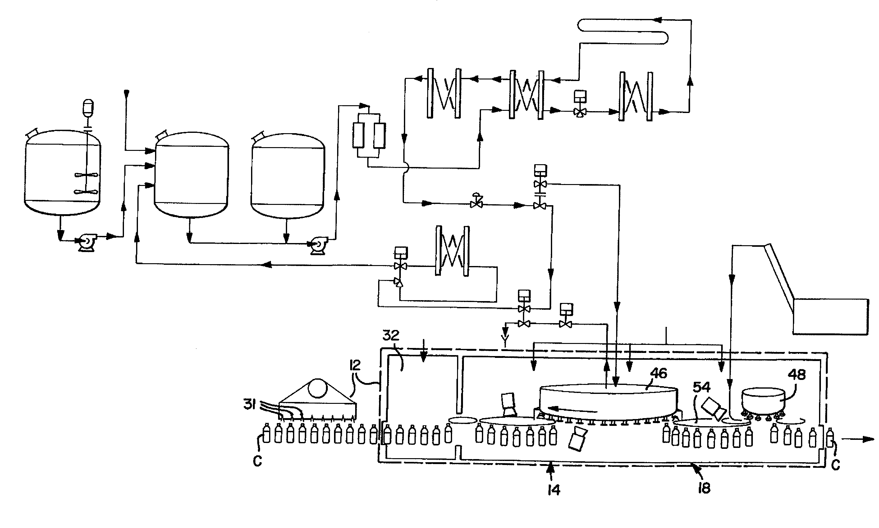
[0054]Referring now to the FIGS., and initially to FIGS. 4-6, there is shown an exemplary embodiment of an apparatus for sterile filling of containers, generally designated with the reference numeral 10. In one exemplary embodiment, the containers are beverage containers, although the system 10 can be used in various other container applications requiring sterile filling and closing. The system 10 generally includes a first module, or station 12 and a second module or station 14. The first station 12 and the second station 14 have certain associated structures 16, as explained...


PUM

PropertyMeasurementUnit
diameteraaaaaaaaaa
diameteraaaaaaaaaa
areaaaaaaaaaaa

Abstract

An apparatus for sterile filling of beverage containers has a first module and a second module. The first module rinses and sterilizes empty containers and delivers the sterilized containers to the second module. The second module fills and caps the containers with beverage product at ambient temperature in an active sterilization zone utilizing an e-beam sterilization unit.

Description

RELATED APPLICATIONS[0001]This application claims priority to and the benefit of and is a continuation-in-part of U.S. Application No. 60 / 949,149 filed on Jul. 11, 2007 entitled “Apparatus and Method for Sterile Filling of Beverage Containers,” which is incorporated herein by reference and made a part hereof.TECHNICAL FIELD[0002]An exemplary embodiment disclosed herein relates to sterile filling of beverage containers, and in particular, an in-line filling apparatus that creates an active sterilization zone in a confined hygienic environment (“CHE”) for filling and closing containers.BACKGROUND OF THE INVENTION[0003]Various types of beverages or products are stored in different types of containers for eventual consumption by consumers. Beverages and other products are typically filled in containers such as thermoplastic or glass liquid containers in an automated filling process. The product, the container, and container closure, such as a cap, must all be sterilized, or free from mi...

Claims


Application Information

Patent Timeline
Patent Type & Authority Applications(United States)
IPC IPC(8): B65B55/08B65B3/04B65B7/28
CPCA61L2/082A61L2/087A61L2202/23B67C3/22B67C2003/2688B67C7/0053B67C7/0073B67C2003/228B67C3/242
Inventor MASTIO, MICHAEL J.WU, REI-YOUNG AMOSMCGOWAN, MICHAEL F.RANIWALA, SUBODH K.SCHIMMEL, GREGORYSCHUMAN, JAMES D.POWELL, RICHARD O.
Owner STOKLEY VAN CAMP INC
Why Eureka
Try Eureka