Two-stage decompression ejector and refrigeration cycle device

a decompression ejector and cycle device technology, applied in the direction of machines/engines, transportation and packaging, light and heating equipment, etc., can solve the problem of increasing the noise level nl

Inactive Publication Date: 2009-01-15
DENSO CORP
View PDF2 Cites 24 Cited by
  • Summary
  • Abstract
  • Description
  • Claims
  • Application Information

AI Technical Summary

Benefits of technology

[0029]According to a second aspect of the present invention, an ejector-type refrigeration cycle device includes the two-stage decompression ejector according to the first aspect of the present invention. Accordingly, the low-frequency abnormal noise generated at the two-stage decompression ejector on startup of the ejector-type refrigeration cycle device can be prevented.

Problems solved by technology

It is found that the increase in noise level NL is caused by high-frequency noise, such as frictional noise, generated when the refrigerant passes through the cycle.

Method used


Image

  • Two-stage decompression ejector and refrigeration cycle device
  • Two-stage decompression ejector and refrigeration cycle device
  • Two-stage decompression ejector and refrigeration cycle device

Examples


first embodiment

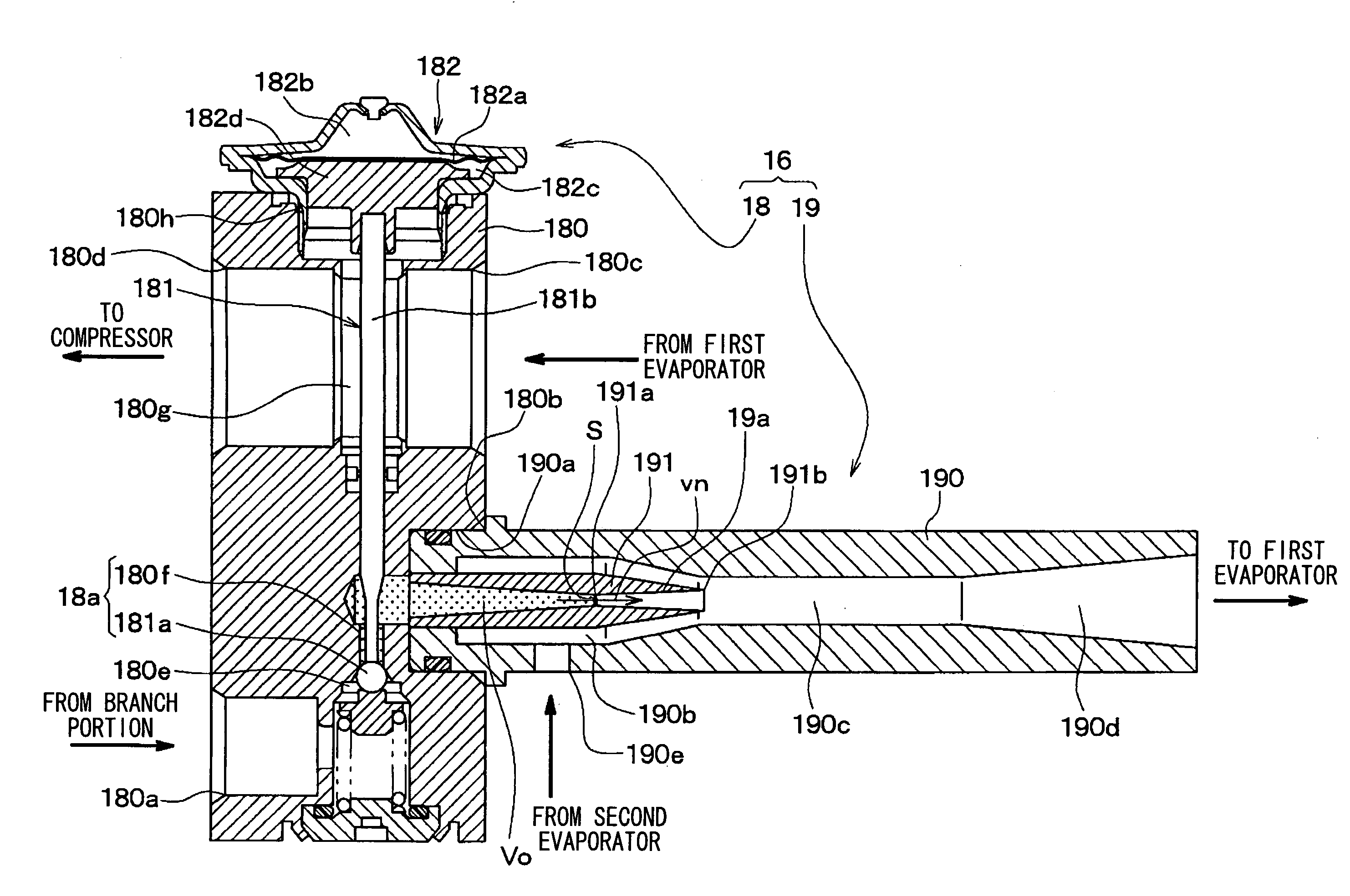
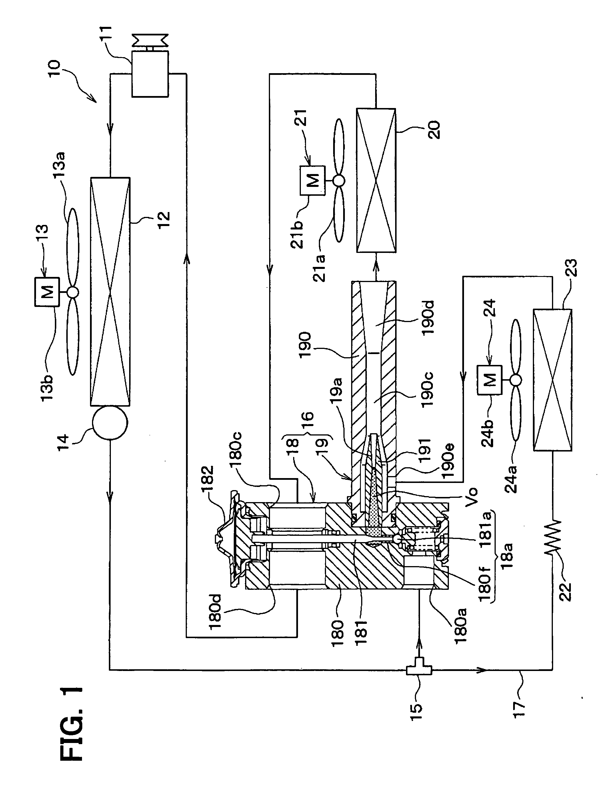
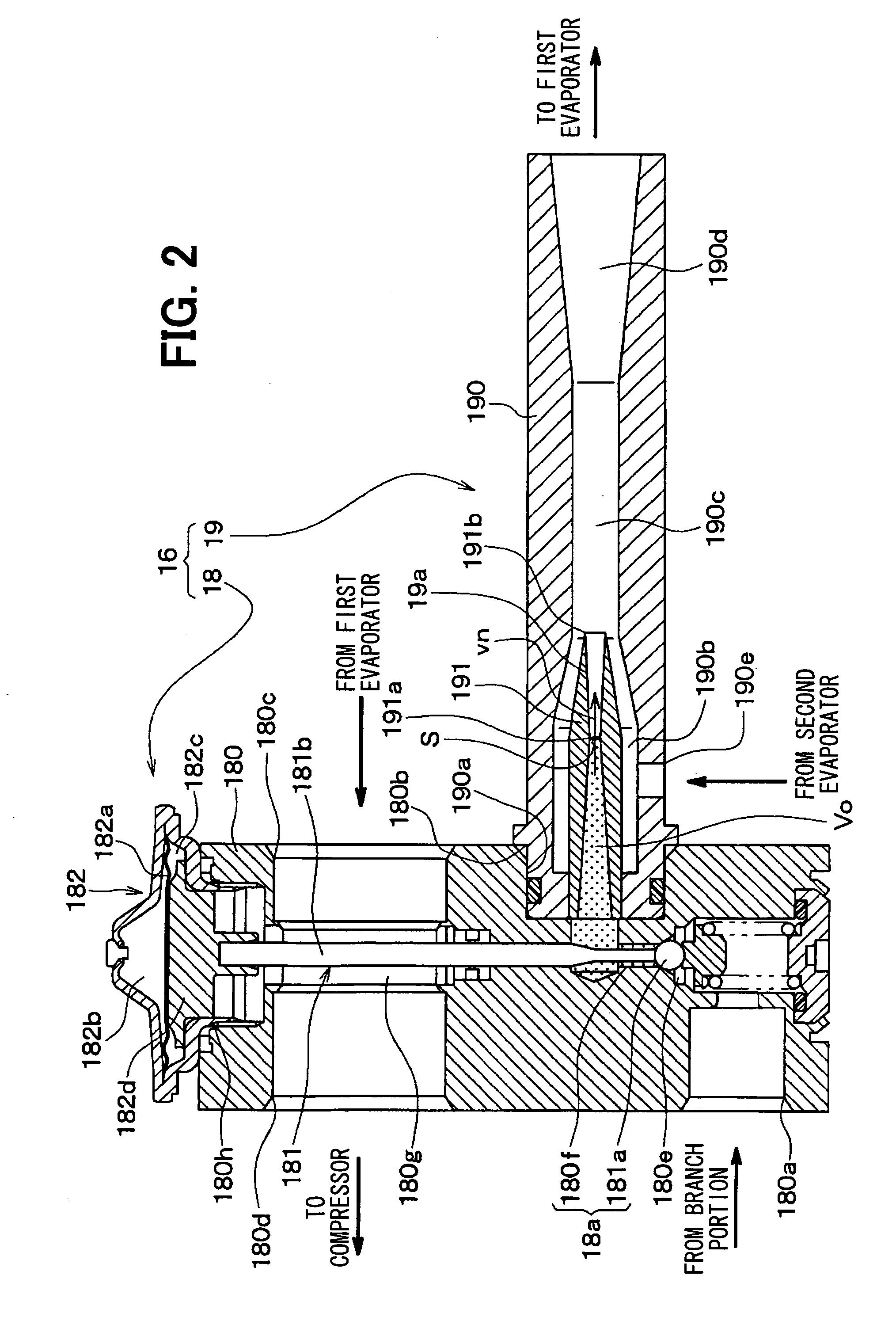
[0042]A first embodiment of the present invention will be described below with reference to FIGS. 1 and 2. In the present embodiment, an ejector-type refrigeration cycle device 10 including a two-stage ejector 16 of the invention is applied to an air conditioner for a vehicle. FIG. 1 shows the entire configuration of the ejector-type refrigeration cycle device 10. In the ejector-type refrigeration cycle device 10, a compressor 11 for sucking and compressing refrigerant is rotatably driven by a vehicle engine (not shown) by an electromagnetic clutch, a belt, or the like.

[0043]As the compressor 11, may be used either of a variable displacement compressor for being capable of adjusting a refrigerant discharge capacity depending on a change in discharge capacity, or a fixed displacement compressor for adjusting a refrigerant discharge capacity by changing an operating efficiency of the compressor by intermittent connection of the electromagnetic clutch. The use of an electric compressor...

second embodiment

[0095]In the first embodiment, the thermal expansion valve 18 and the ejector 19 are integrally connected together to form the two-stage decompression ejector 16. Alternatively, in the present embodiment, a thermal expansion valve and an ejector are integrally formed as shown in FIGS. 3 and 4 thereby to construct a two-stage decompression ejector 26. FIGS. 3 and 4 illustrate the same or equivalent components as those of the first embodiment by the same reference numerals. The same goes for the following drawings.

[0096]FIG. 3 is a diagram showing the entire configuration of the ejector-type refrigeration cycle device 10 of the present embodiment. FIG. 4 is a sectional view of the two-stage decompression ejector 26. The two-stage decompression ejector 26 of the present embodiment includes a housing 260 corresponding to the thermal expansion valve 18 of the first embodiment, a needle valve 261, a temperature sensing portion 262, a body 190 corresponding to the ejector 19 of the first e...

third embodiment

[0107]In the second embodiment, the two-stage decompression ejector 26 operates the needle valve 261 by use of the temperature sensing portion 262 serving as a superheat-degree actuated mechanism to adjust a throttle passage area of the variable throttle mechanism 26a such that the superheat degree of the refrigerant on the outlet side of the first evaporator 20 becomes a predetermined value. In the present embodiment, as shown in the entire configuration diagram of FIG. 5, a two-stage decompression ejector 27, which can electrically control the operation of the needle valve 261, is used.

[0108]In the two-stage decompression ejector 27 of the present embodiment, the needle valve 261 is driven by an electric actuator 270. As the electric actuator 270, for example, a motor actuator, such as a stepping motor, or an electromagnetic solenoid mechanism can be employed.

[0109]The electric actuator 270 is driven and controlled by a control signal output from a controller 30. The controller 30...


PUM


Abstract

A two-stage decompression ejector includes a variable throttle mechanism having a first throttle passage for decompressing a fluid and a valve body for changing a throttle passage area of the first throttle passage, a nozzle having therein a second throttle passage for further decompressing the fluid decompressed by the variable throttle mechanism, and a suction portion for drawing a fluid by a suction effect of a high-velocity jet fluid from the nozzle. The formula of 0.07≦Vo×S/vn≦0.7 is satisfied, in which Vo is an intermediate-pressure space volume (mm3) from an outlet of the variable throttle mechanism to an inlet of the second throttle passage, S is a throttle passage sectional area (mm2) of a minimum passage sectional area portion of the second throttle passage, and vn is a flow velocity (mm/s) of the fluid passing through the minimum passage sectional area portion.

Description

CROSS REFERENCE TO RELATED APPLICATION[0001]This application is based on Japanese Patent Application No. 2007-153806 filed on Jun. 11, 2007, the contents of which are incorporated herein by reference in its entirety.FIELD OF THE INVENTION[0002]The present invention relates to a two-stage decompression ejector for decompressing and expanding a fluid by using two throttles, and a refrigeration cycle device including the two-stage decompression ejector.BACKGROUND OF THE INVENTION[0003]A refrigeration cycle device is conventionally proposed which uses an ejector as decompression means for decompressing and expanding refrigerant.[0004]This kind of ejector-type refrigeration cycle device is designed to draw refrigerant flowing from an evaporator by a suction effect of a refrigerant flow jetted at a high velocity from a nozzle of an ejector, and to increase a refrigerant pressure to be drawn into a compressor by a diffuser of the ejector. Thus, the refrigerant pressure to be drawn into the...

Claims


Application Information

Patent Timeline
Patent Type & Authority Applications(United States)
IPC IPC(8): F25B1/06
CPCF25B41/00F25B2500/12F25B2500/01F25B2341/0012F25B2341/0013F25B2341/0683F25B2700/21151B60H2001/3298
Inventor OSHITANI, HIROSHITAKANO, YOSHIAKIGOCHO, MIKA
Owner DENSO CORP
Why Eureka
Try Eureka