Micro-electro-mechanical pressure sensor

a micro-electro-mechanical and pressure sensor technology, applied in the direction of fluid pressure measurement, measurement devices, instruments, etc., can solve the problems of increasing the cost, complicated circuits of micro-electro-mechanical (i.e., mem) pressure sensors, and small voltage-loading capability of sensing parts

Active Publication Date: 2009-01-15
TSINGHUA UNIV +1
View PDF6 Cites 36 Cited by
  • Summary
  • Abstract
  • Description
  • Claims
  • Application Information

AI Technical Summary

Benefits of technology

[0006]What is needed, therefore, is a micro-electro-mechanical pressure sensor, which has a vibrating membrane containing carbon nanotube structures.

Problems solved by technology

However, a voltage-loading capability of the sensing part is very small.
This makes circuits of the micro-electro-mechanical (i.e., MEM) pressure sensor complicated, thereby adding to the cost thereof.
But so far, carbon nanotubes have not been exploited for use in micro-electro-mechanical pressure sensors.

Method used


Image

  • Micro-electro-mechanical pressure sensor
  • Micro-electro-mechanical pressure sensor
  • Micro-electro-mechanical pressure sensor

Examples


first embodiment

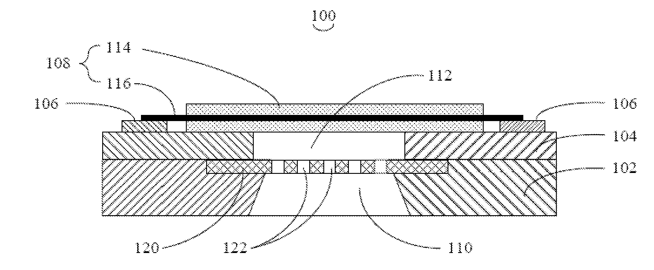
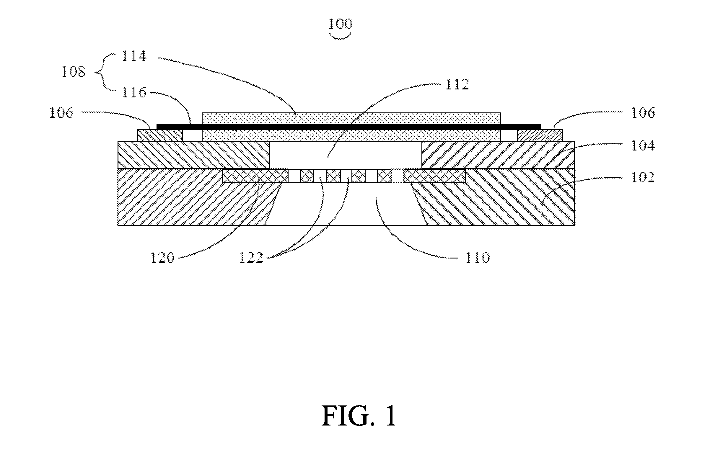
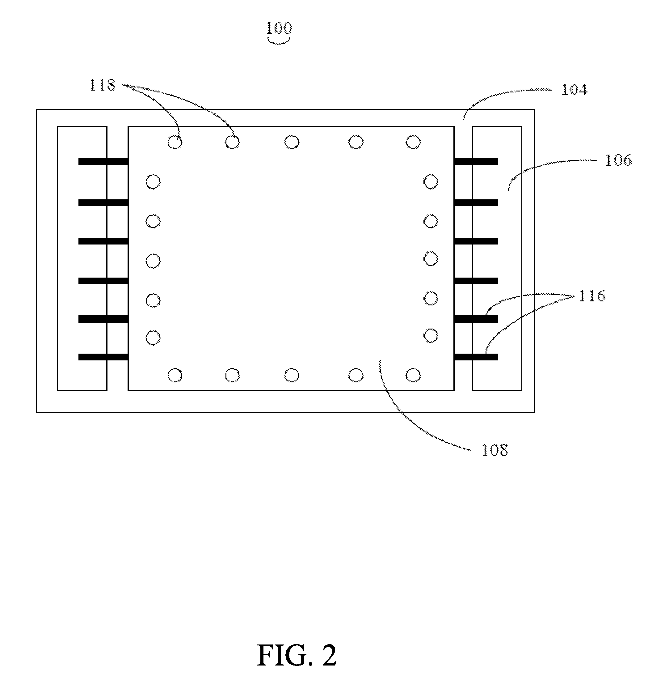
[0020]Referring to FIGS. 1 and 2, a pressure sensor 100 is provided in the The pressure sensor 100 includes a substrate 102, a dielectric isolation layer 104, two electrodes 106, and a vibrating membrane 108. The dielectric isolation layer 104 is formed on the substrate 102. The electrodes 106 and the vibrating membrane 108 are disposed on the dielectric isolation layer 104.

[0021]The substrate 102 is composed, at least, of one or more semiconductor materials. A material of the substrate is selected from a group consisting of doped n-type silicon, p-type silicon, and intrinsic silicon. Further, an acoustic cavity 110 is formed by etching on a backside of the substrate 102. The acoustic cavity 110 is configured for enhancing the sensitivity of the pressure sensor 100.

[0022]The dielectric isolation layer 104 includes a through hole 112. The through hole 112 is disposed so as to coincide / align with the acoustic cavity 110. Quite usefully, the material of the dielectric isolation layer ...

seventh embodiment

[0035]A pressure sensor (not shown) is provided in a The pressure sensor is similar to the above-described pressure sensor. But, the vibrating membrane includes a plurality of super-aligned arrays of carbon nanotubes or other arrays of carbon nanotubes. Each of the arrays of carbon nanotubes includes a plurality of oriented carbon nanotubes. The oriented carbon nanotubes in all the arrays of carbon nanotubes are parallel to each other. Changes of pressure on the vibrating membrane cause deformation of the arrays of carbon nanotubes along an axis of the arrays of carbon nanotubes, thereby causing changes of resistance therein. The changes of resistance are detected by an external circuit, which is connected to the array of carbon nanotubes. As such, mechanical deformation of the vibrating membrane is changed into electrical signals. The electrical signals are output by the external circuit.

eighth embodiment

[0036]A pressure sensor (not shown) is provided in an The pressure sensor is similar to the above-described pressure sensor. In this embodiment, though, the carbon nanotube structures of the vibrating membrane are carbon nanotube films. The carbon nanotube films are separately arranged in parallel on a same plane. Each of the carbon nanotube films includes a plurality of carbon nanotube bundles. Each of the carbon nanotube bundles includes a plurality of carbon nanotubes arranged in a preferred orientation. Adjacent carbon nanotube bundles are combined by van der Waals attractive force to connect with each other. Quite suitably, the orientations of carbon nanotube bundles in all the carbon nanotube films are parallel. Changes of pressure on the vibrating membrane cause deformation of the carbon nanotube films along an axis of the carbon nanotube films, thereby causing changes of resistance therein. The changes of resistance are detected by an external circuit, which is connected to...


PUM

PropertyMeasurementUnit
angleaaaaaaaaaa
thicknessaaaaaaaaaa
angleaaaaaaaaaa

Abstract

The present micro-electro-mechanical pressure sensor includes a substrate, a dielectric isolation layer, at least two electrodes, and a vibrating membrane. The substrate includes an acoustic cavity. The dielectric isolation layer is formed on the substrate, and the dielectric isolation layer includes a through hole corresponding to the acoustic cavity. The at least two electrodes are separately formed on the dielectric isolation layer. The vibrating membrane covers the through hole, and the vibrating membrane includes at least one carbon nanotube structure with two opposite ends. The two opposite ends of the carbon nanotube are respectively connected to at least a given one of the at least two electrodes.

Description

BACKGROUND[0001]1. Field of the Invention[0002]The invention generally relates to devices of micro-electro-mechanical systems, and, particularly, to a micro-electro-mechanical pressure sensor.[0003]2. Discussion of Related Art[0004]A micro-electro-mechanical pressure sensor generally includes a sensing part and an application specific integrated circuit (ASIC) part. The sensing part has a vibrating membrane, which vibrates to sound. However, a voltage-loading capability of the sensing part is very small. Thus, the sensing part usually connects with an amplifier, which is used to provide high resistance input and low noise. This makes circuits of the micro-electro-mechanical (i.e., MEM) pressure sensor complicated, thereby adding to the cost thereof.[0005]One prerequisite for this vibrating membrane is that it be as sensitive as possible. One useful method is to improve a compliance degree of the vibrating membrane. Carbon nanotubes have very good mechanical properties and piezoresis...

Claims


Application Information

Patent Timeline
Patent Type & Authority Applications(United States)
IPC IPC(8): G01L9/00
CPCG01L9/0019G01L9/0016
Inventor QIAO, DONG-HAIYAO, YUANJIANG, KAI-LILIU, LIANG
Owner TSINGHUA UNIV
Why Eureka
Try Eureka