Lubrication system for an engine

a technology for lubricating systems and engines, applied in the direction of lubrication for crankcase compression engines, pressure lubrication, combustion engines, etc., can solve the problems of phased out two-stroke engines and serious problems such as lubrication

Active Publication Date: 2009-01-15
LIN SZU LIANG
View PDF7 Cites 52 Cited by
  • Summary
  • Abstract
  • Description
  • Claims
  • Application Information

AI Technical Summary

Benefits of technology

[0006]It is therefore one object of the invention to provide a lubrication system for a small lightweight four-stroke engine and the lubrication system, provided with a weight at one end of a flexib

Problems solved by technology

Gradually, two-stroke engines are phased out due to heavy harmful exhaust emissions (e.g., hydrocarbon (HC)).
Lubrication becomes a very se

Method used


Image

  • Lubrication system for an engine
  • Lubrication system for an engine
  • Lubrication system for an engine

Examples


Embodiment Construction

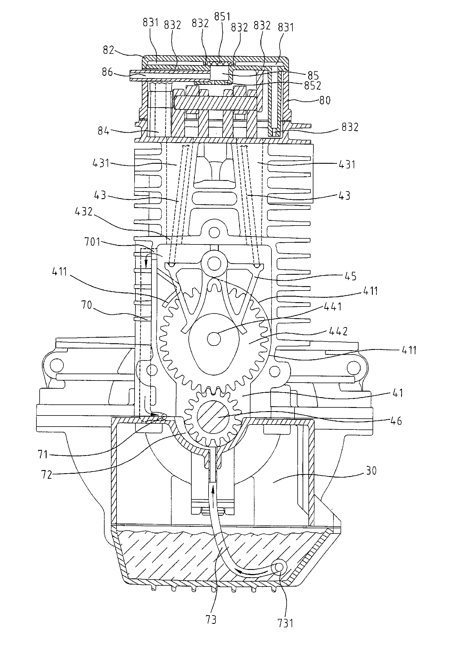
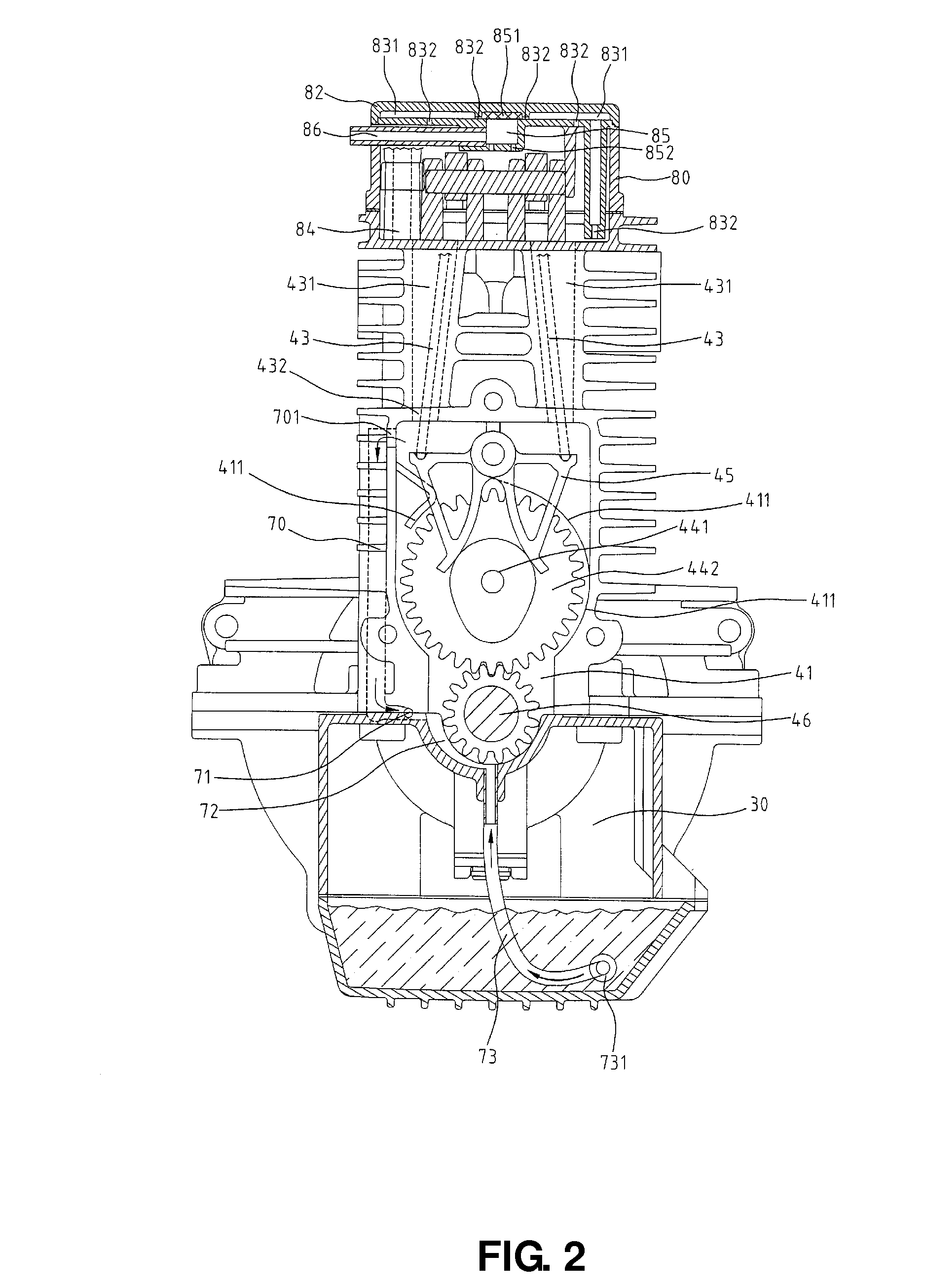
[0018]Referring to FIGS. 1 to 10, a four-stroke internal combustion engine (ICE) in accordance with a preferred embodiment of the invention is shown. The engine is constructed as a lightweight housing and comprises the following components. Each component is discussed in detail below.

[0019]A crankcase 10 is provided. An oil reservoir 30 is provided. A check valve case 20 is provided in fluid communication with both the crankcase 10 and the oil reservoir 30. A first branch tube 60 is in fluid communication with both the check valve case 20 and a gaseous oil tube 42 which is connected to a cam actuation section 40. A first venturi 61 is provided proximate a joining portion of the cam actuation section 40 and the gaseous oil tube 42. Note that the number of the first venturi 61 may be more than one depending on applications. A second branch tube 70 is provided between the crankcase 10 and a camshaft case 41 of the cam actuation section 40 and is in fluid communication therewith. A seco...


PUM


Abstract

A lubrication system for a small lightweight four-stroke engine is disclosed. The lubrication system, provided with a weight at one end of a flexible oil tube inserted into an oil reservoir, is capable of providing a sufficient lubrication to components of the engine which may operate in a horizontal posture, a vertical posture, or any posture therebetween.

Description

BACKGROUND OF THE INVENTION[0001]1. Field of Invention[0002]The invention relates to four-stroke internal combustion engine (ICE) and more particularly to an improved lubrication system for a small lightweight four-stroke engine.[0003]2. Description of Related Art[0004]Portable power tools such as lawn movers, line trimmers, chain saws as mostly powered by two-stroke ICEs in earlier days. Gradually, two-stroke engines are phased out due to heavy harmful exhaust emissions (e.g., hydrocarbon (HC)). Nowadays, almost all such portable power tools are powered by four-stroke ICEs.[0005]Lubrication becomes a very serious problem since portable power tools are required to operate in a wide range of orientations (i.e., being tilted or even upside down). There have been numerous suggestions in prior patents for solving this problem. For example, U.S. Pat. No. 7,287,508 discloses an engine lubrication method which is incorporated herein by reference. Thus, continuing improvements in the exploi...

Claims


Application Information

Patent Timeline
IPC IPC(8): F01M3/04
CPCF01M1/04F01M13/00F01M2001/126F01M11/064
Inventor LIN, SZU LIANG
Owner LIN SZU LIANG
Why Eureka
Try Eureka