Inhalant exposure system

a technology which is applied in the field of inhalant exposure system to achieve the effects of enhancing preventing the loss and not impede the flow of inhalant and exhalation

Inactive Publication Date: 2009-01-15
BATTELLE MEMORIAL INST
View PDF15 Cites 6 Cited by
  • Summary
  • Abstract
  • Description
  • Claims
  • Application Information

AI Technical Summary

Benefits of technology

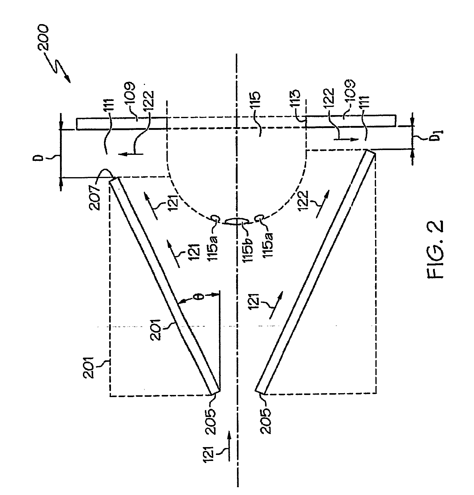
[0006]A yet further embodiment of the invention provides for an inhalant exposure unit having a housing 301 positioned around a central axis having an inlet end and an outlet end. The housing typically forms at least in part a truncated cone. The sides of the truncated cone form an angle θ with respect to the central axis. Typically the angle θ has a value of about 0° to about 60°. A face plate is positioned vertical to the central axis at the outlet end of the housing but not in contact therewith. An annular outlet is formed by the spaced apart relationship of the outlet end and face plate. An outer housing located concentrically around the axis and housing. The outer housing and the housing together form an exhaust passage between them. The outer housing has a back end that corresponds to the inlet end of housing and a front end that aligns with the outlet end of the housing. The front end of the outer housing, however, makes contact with the face plate in a sealing relationship to prevent the loss of inhalant and exhaled breath. The face plate has an axial opening for admitting at least a portion of an animal's head. Typically the animal's head is admitted through the axial opening into the exposure volume around the animals head. The benefits of the invention are obtained by having the flow of inhalant flow past the nostrils and / or mouth of the animal and sweep exhaled breath away from the animal's nostrils or mouth and into the annular outlet. The annular outlet is typically unimpeded by supports and the like so as to not impede the flow of inhalant and exhaled breath. In some embodiments, however, there may be one to several struts or supports (not shown) such as those typically used in the art, that do not substantially interfere with the flow of inhalant and exhaled breath through the annular outlet. The conical shape of housing provides for enhanced flow of inhalant past the animal's head compared to the embodiment that does not use a truncated cone. All embodiments, however, provide for substantially unimpeded flow of inhalant in a 360° pattern around the animal's head so as to sweep exhaled air away from the animal's nostrils and / or mouth. The inhalant and exhaled breath flow into annular outlet and then through the exhaust passage to an outlet. A flow restrictor may be used to further control the flow of inhalant and exhaled breath to the exhaust outlet.

Problems solved by technology

Both embodiments, however, provide for substantially unimpeded flow of inhalant in a 360° pattern around the animal's head so as to sweep exhaled air away from the animal's nose and mouth.
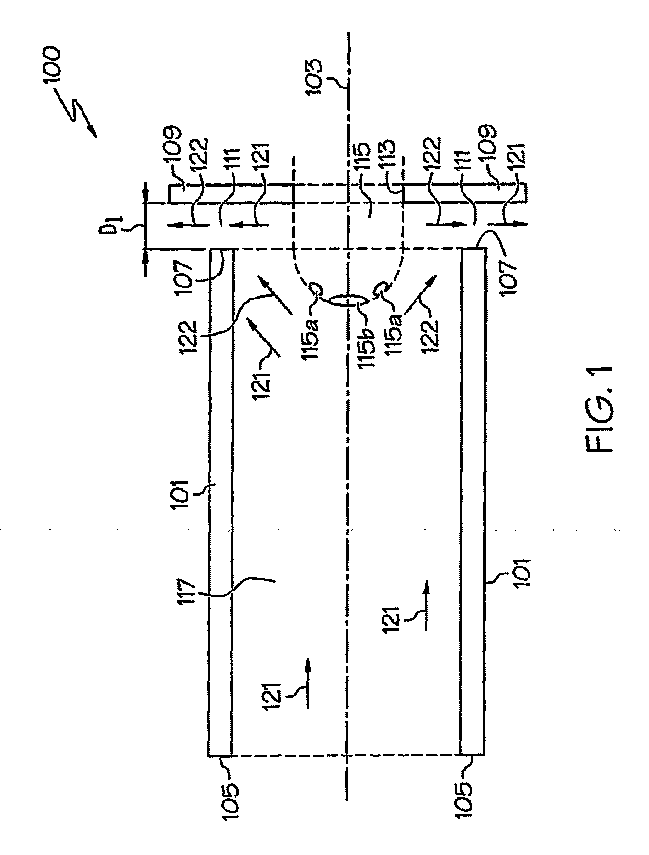
All embodiments, however, provide for substantially unimpeded flow of inhalant in a 360° pattern around the animal's head so as to sweep exhaled air away from the animal's nostrils and / or mouth.

Method used


Image

  • Inhalant exposure system
  • Inhalant exposure system
  • Inhalant exposure system

Examples


example 1

[0043]A laboratory scale inhalant exposure system for providing an inhalant such as an aerosol to animals was built in accordance with the figures. The inhalant exposure system was constructed of Plexiglas™ (although any plastic or metal inert to the test materials will work) and consisted of a 2.54 cm inside diameter tube with a 5.08 cm outside diameter of approximately 56 cm long. The end of the tube was mated with a 10.2 cm long and 5.1 cm inside diameter solid stock of Plexiglas™ with a 10.2 cm outside diameter. The end of the tube was lathed at 30° to form a truncated cone radiating out from the 2.54 cm (1 inch) diameter inner tube, to the 10.2 cm (4 inch) diameter outer tube for the insertion of the animals nose through a rubber dam. A 15.25 cm (6 inch) outside diameter and 12.7 cm (5 inch) inside diameter tube was mounted concentrically with front and back plates around the 10.2 cm (4 inch) diameter tube for exhausting the aerosol from the system. The face plate, located arou...

example 2

Multiple Animal Inhalation Exposure System

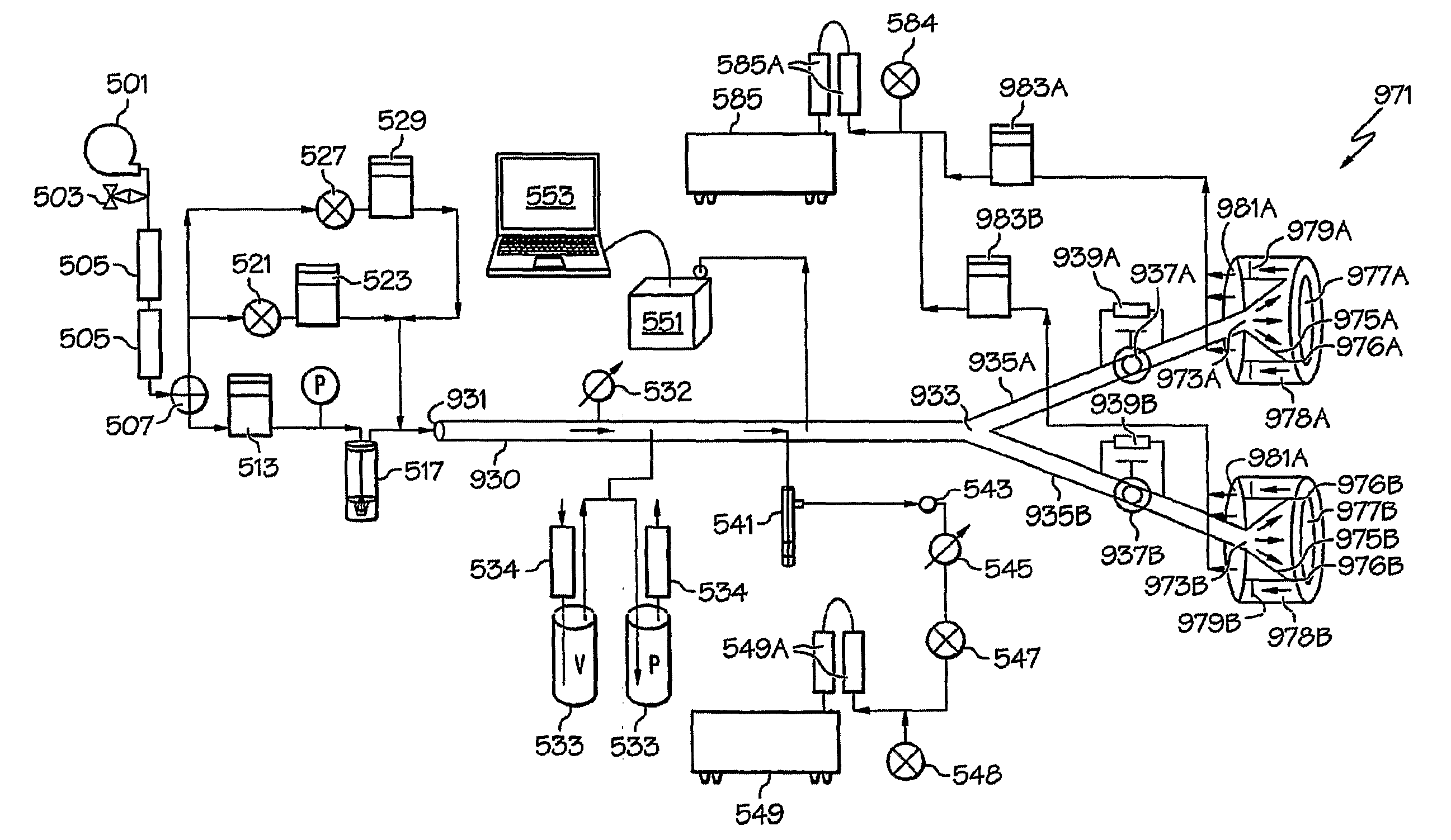
[0058]The multiple inhalation exposure system (FIG. 9 ) was constructed of Plexiglas, and consisted of a 2.54 cm inside diameter tube with a 5.08 cm outside diameter of approximately 56 cm long. The end of the tube was mated with a Y tubing connector with an inside diameter of 1.9 cm. The Y tubing connector is utilized to divert the challenge aerosol to two separate exposure sites. Two 50 cm long sections of flexible Tygon™ tubing with a 1.9 cm inside diameter are connected to each port of the Y connector. The two sections of Tygon™ tubing were in turn connected to two ball valves (also known as isolation valves) that are each attached to an exposure unit. The ball valves would be utilized in actual exposure challenges to turn off the exposure challenge to one of the exposure units and animal model based on inhaled volume while continuing to deliver the exposure challenge to the other exposure unit. By tuning the ball valve off, the aerosol ...

example 3

[0065]Aerosol Challenge (Nebulizer) Suspension Enumeration: The challenge spore suspensions (B. anthracis) were prepared by diluting the stock suspension to a targeted concentration. The challenge spore suspension was enumerated by serial dilution of the challenge suspension by spreading 0.1 mL on each of five tryptic soy agar plates for three different dilutions. The tryptic soy agar plates were placed in a secondary container and incubated at 37° C. for 16-24 hours. After the incubation period, the number of colonies on each plate was counted. Each concentration was determined by the spread plate method.


PUM


Abstract

An inhalant exposure unit and system that provides controlled flow of inhalant to an animal with a breathing system that provide controlled exposure of inhalant, minimized breathing of exhaled air and control of exhaust flow.

Description

FIELD OF THE INVENTION[0001]The invention provides a method and apparatus for controlled testing of single and multiple animals with selected inhalants. The invention provides for reduced rebreathing of exhaled breath.BACKGROUND OF THE INVENTION[0002]Various inhalation exposure apparatus have been developed for providing controlled levels of inhalants to animals with the purpose of determining the impact on the animals. One of the primary considerations for inhalation exposure systems is that the inhaled materials be of the same concentration so that biological effects observed on the teat animals can be correlated and reproducibly obtained.[0003]Recent world events have lead to increased concern of potential terrorist biological warfare attacks. One of the main biological warfare threats to humans is inhalational exposure to pathogenic bioaerosols. Examples of infectious diseases known to be caused by aerosolized bacteria are tuberculosis, legionellosis, and anthrax. Bacteria are s...

Claims


Application Information

Patent Timeline
Patent Type & Authority Applications(United States)
IPC IPC(8): A61M16/00A01K1/03
CPCA61D7/04
Inventor BARNEWALL, ROY EDMUNDTUTTLE, RICHARD SCOTT
Owner BATTELLE MEMORIAL INST
Why Eureka
Try Eureka