Supercharge Your Innovation With Domain-Expert AI Agents!

Electrical Cable Support Bracket

Inactive Publication Date: 2009-01-15
FORBIS ROBERT C
View PDF12 Cites 10 Cited by
  • Summary
  • Abstract
  • Description
  • Claims
  • Application Information

AI Technical Summary

Benefits of technology

[0014]An advantage of the present invention is that it provides a cable support bracket with integral spacers which separate the cable restraints, and corresponding cables, a minimum distance from an interior wall, such as one formed of drywall.
[0015]Another advantage of the present invention is that it can accommodate a variety of different cable types, such as three (or more) wire power cables; multi-wire service entrance cables; as well as larger feeder cables.
[0016]Yet another advantage of the present invention is that it does not require an electrician and / or installer to fabricate a custom bracket.
[0017]Yet another advantage of the present invention is that it does not require special tools, such as an electric power saw or other power tool, for installation.
[0018]Yet another advantage of the present invention is that it is cost effective to manufacture.
[0019]Yet another advantage of the present invention is that it saves the electrician's and / or installer's time during the installation of an electrical box or panel.

Problems solved by technology

While these approaches may work as intended, they are very time consuming.
Complying with this requirement further increases the time and effort needed to fabricate and install the custom bracket.
While the disclosed method and tooling device are both suitable for their intended purpose of manufacturing a wiring harness made up of individual wires, they are not suitable for producing harnesses capable of holding three-wire, and larger, cables above an electrical box.
First, the clips for the disclosed harness are not suitable for holding larger diameter cables.
Second, there are no elements provided to facilitate mounting of the harness to a wall.
Third, there are no provisions for ensuring the required 1¼ inches of spacing to reduce the likelihood of inadvertent contact with screws and nails.
Although this device is useful as a splicing fixture, it has the same drawbacks as the '949 patent for use as a cable support bracket.
These devices and methods are suitable for their intended purposes, but each is deficient in some way for use as a cable support bracket.

Method used


Image

  • Electrical Cable Support Bracket
  • Electrical Cable Support Bracket
  • Electrical Cable Support Bracket

Examples


Embodiment Construction

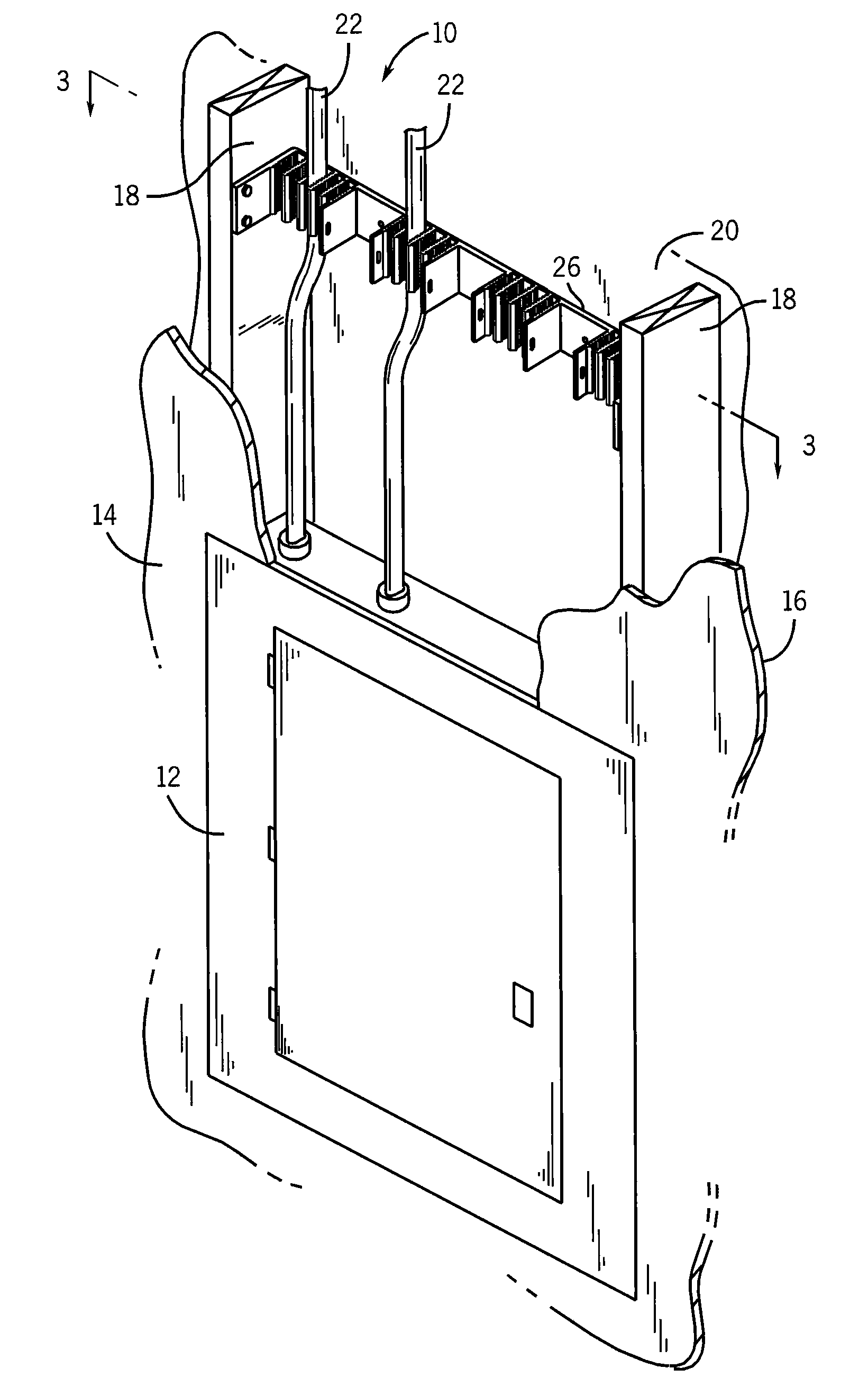
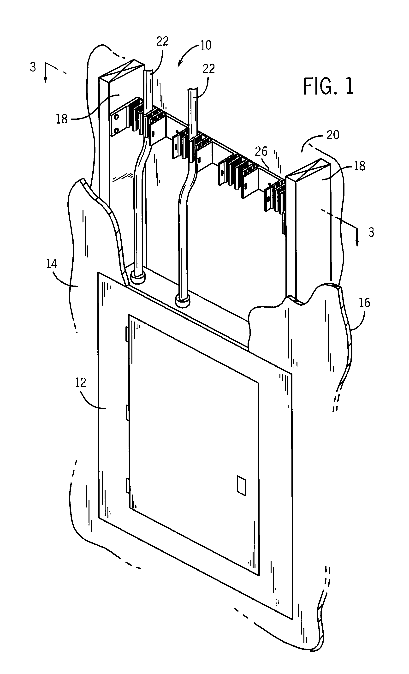
[0033]Referring now to the drawings, an electrical arrangement 10 includes an electrical enclosure, or box, 12 mounted in close proximity to a first wall 14, such as an interior wall formed of drywall having an inner surface 16. The electrical box 12 and drywall 14 may be mounted to a pair of adjacent studs 18, which are themselves secured to a second wall 20, such as a concrete or masonry exterior or structural wall. A number of multi-wire cables 22, 24 (see FIG. 4) extend from the electrical box 12 and are secured to and supported by a cable support bracket 26 constructed in accordance with an exemplary embodiment of the present invention. The cables 22, 24 extend into and are terminated inside of the electrical box 12 with any number of various electrical termination devices (not shown), including, but not limited to, circuit breakers, fuse blocks, terminal strips, connectors, transformers, controllers and other similar electrical terminating components.

[0034]The first, smaller, ...


PUM


Abstract

A cable support bracket includes a backplate with a number of structures extending transversely therefrom and defining a plurality of cable restraints and slots. The cable restraints have a series of projections formed on the transversely extending structures. Each cable restraint has a series of projections aligned so as to create matching barbs that secure electrical cables within the restraints. At least one transversely-extending structure acts as a spacer to ensure that electrical safety requirements regarding the distance between cables and internal walls are met when the bracket is installed.

Description

CROSS REFERENCE TO RELATED APPLICATIONS[0001]This application claims priority to U.S. Provisional Patent Application No. 60 / 948,575 filed on Jul. 9, 2007, the contents of which are hereby incorporated by reference as if fully set forth herein in their entirety.STATEMENT REGARDING FEDERALLY SPONSORED RESEARCH[0002]Not applicable.BACKGROUND OF THE INVENTION[0003]The present invention generally relates to the installation and mounting of electrical wires and cables. In particular, the present invention relates to vertically-mounted support brackets suitable for securing electrical wires or optical cables thereto. Even more particularly, this invention relates to wall-mounted support brackets which secure cables and wires in close proximity to electrical enclosure in compliance with electrical safety standards.[0004]Certain electrical safety standards dictate the proper installation and securing means for wiring and cabling entering and exiting enclosures, such as an electrical circuit ...

Claims


Application Information

Patent Timeline
IPC IPC(8): H02B1/40
CPCH02G3/32
Inventor FORBIS, ROBERT C.
Owner FORBIS ROBERT C
Features
  • R&D
  • Intellectual Property
  • Life Sciences
  • Materials
  • Tech Scout
  • Unparalleled Data Quality
  • Higher Quality Content
  • 60% Fewer Hallucinations
Learn More