Power supply voltage booster

a technology of power supply voltage and booster, which is applied in the direction of power conversion systems, electrical control, instruments, etc., can solve the problems of inaccurate operation of fuel injection valve, and achieve the effects of increasing the energy charged to the capacitor, and increasing the charging energy per fixed tim

Inactive Publication Date: 2009-01-15
DENSO CORP
View PDF6 Cites 29 Cited by
  • Summary
  • Abstract
  • Description
  • Claims
  • Application Information

AI Technical Summary

Benefits of technology

[0017]It is therefore an object of the invention to provide a power supply voltage booster capable of avoiding inadequacy of a step-up capability during operation caused by a drop in the power supply voltage or the shortening of the driving time interval of the actuator.

Problems solved by technology

In short, the step-up capability is inadequate, possibly resulting in the inaccurate operation of the fuel injection valve.

Method used


Image

  • Power supply voltage booster
  • Power supply voltage booster
  • Power supply voltage booster

Examples


first embodiment

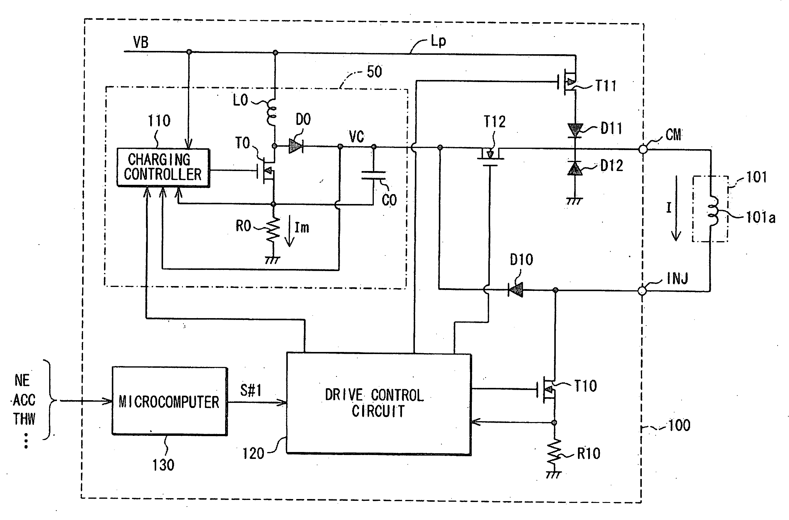
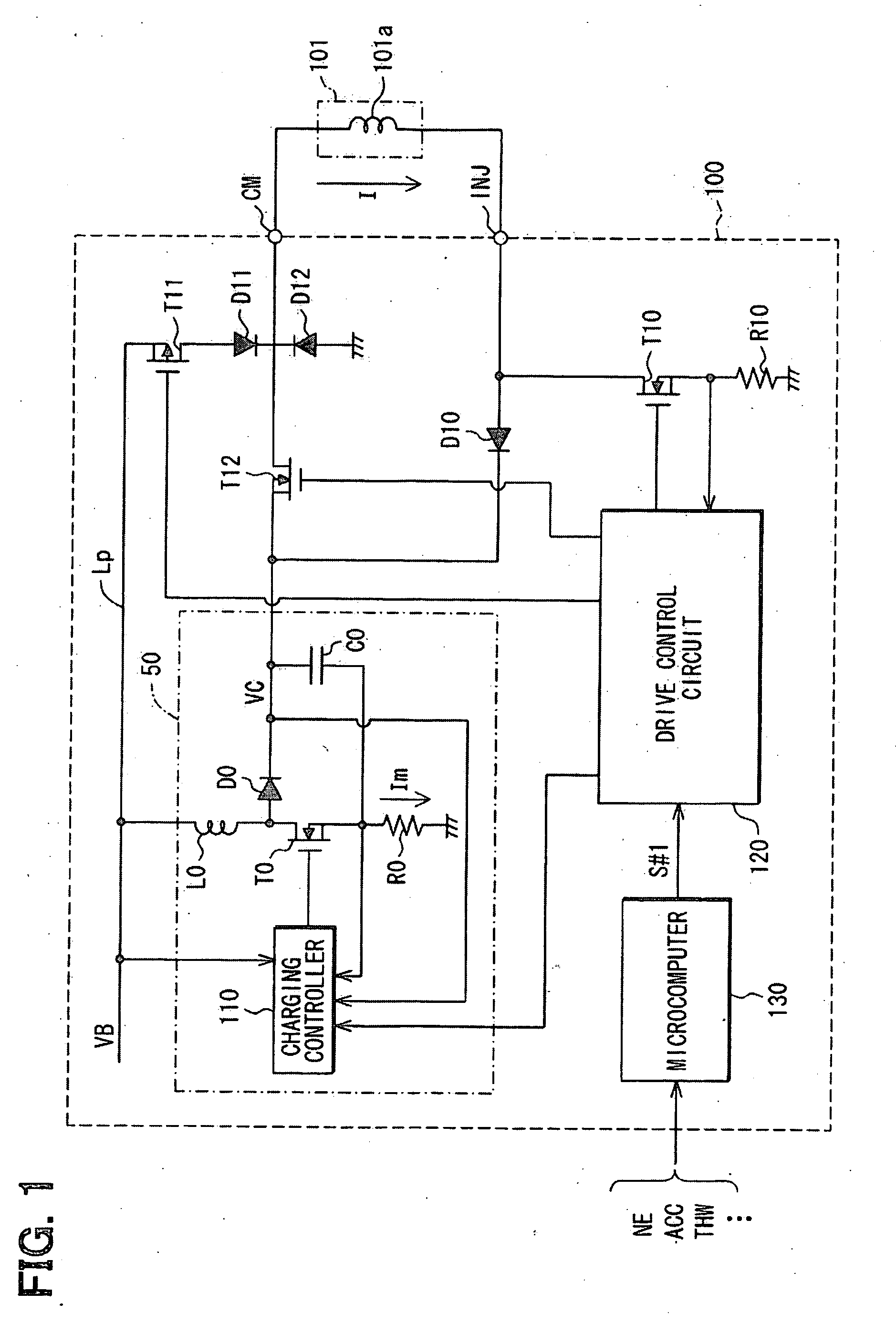
[0091]FIG. 1 is a schematic diagram illustrating a fuel injection controller 100 of a first embodiment where an exemplary injector 101, representing one of the four injectors, and corresponding, for example, to the first cylinder #1, is shown. The driving operation for the injector 101 shown as an example will be described below.

[0092]The injector 101 is of a known solenoid type, which includes a solenoid as a valve opening actuator. Upon application of current to a coil 101a of the solenoid built in the injector 101, the solenoid moves the valve body to the open position, so that the injector 101 is placed in the valve-open mode so as to inject fuel. Upon the ceasing of the application of current to the coil 101a, the valve body moves back to the closed position, so that the injector 101 is placed in the valve-closed mode so as to stop injecting the fuel.

[0093]The fuel injection controller 100 is equipped with a voltage boosting circuit 50 having the same circuit configuration as t...

second embodiment

[0122]The structural components in the following description are designated by using the same reference numerals and phrases as those in a first embodiment, and the other embodiments to be described in greater detail hereinafter.

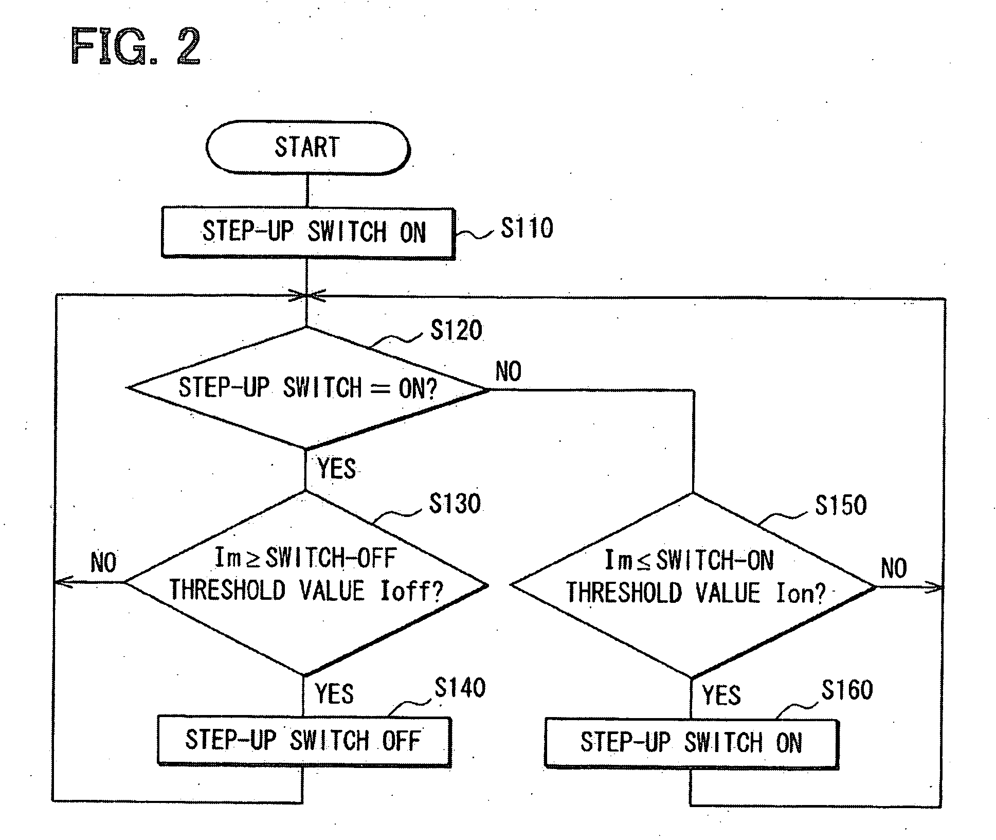
[0123]The fuel injection controller 100 of a second embodiment differs from the fuel injection controller 100 of a first embodiment in that the charging control circuit 110 of the voltage boosting circuit 50 performs processing of setting the switch-on threshold value as illustrated in FIG. 8A in parallel with the processing of the voltage boost switching control illustrated in FIG. 2.

[0124]As shown in FIG. 8A, the charging control circuit 110 detects the battery voltage VB at S210, and then sets a switch-on threshold value Ion for use in the voltage-boost switching control in accordance with the detected value of the battery voltage VB at S230. Specifically, as shown in FIG. 8B, the lower the battery voltage VB, the higher the value at which the switch-on t...

third embodiment

[0129]The fuel injection controller 100 of a third embodiment differs from the fuel injection controller 100 of a first embodiment in at least the following two points.

[0130]First, the charging control circuit 110 of the voltage boosting circuit 50 performs processing of the voltage-boost switching control as shown in FIG. 10 instead of the processing of the voltage-boost switching control as shown in FIG. 2. The charging control circuit 110 turns on the step-up switch T0 at the start of the voltage-boost switching control at S3310. Upon determining that the step-up switch T0 is turned on, corresponding to YES at S320, the charging control circuit 110 waits until an ON elapsed time since the last operation of turning the step-up switch T0 to the on position reaches a time Ton, corresponding to NO at S330. Upon determining that the ON elapsed time reaches the time Ton, corresponding to YES at S330, the charging control circuit 110 turns the step-up switch T0 to the off position at S3...


PUM


Abstract

A power supply voltage booster avoids inadequate step-up capability. In a voltage boosting circuit, a switching device connects and disconnects between the ground potential and one end of the coil, the other end of which is supplied with a supply voltage VB. The switching device is repeatedly turned ON and OFF such that the capacitor is electrically charged from the force in the coil when the switching device is turned off. A charging control circuit turns off the switching device when current flowing through the switching device into the coil is determined to have increased to a switch-off threshold value when the switching device is ON, and turns on the switching device upon determining that the charging current flowing to the capacitor from the coil decreases to a switch-on threshold value when the switching device is OFF. The charging control circuit sets the switch-off threshold value to a larger value as the supply voltage VB is lower. Thus, inadequacy of the step-up capability caused by a drop in the supply voltage VB can be avoided.

Description

CROSS REFERENCE TO RELATED APPLICATIONS[0001]The present application is based on and claims priority to Japanese Patent Application No. 2007-184685, filed Jul. 13, 2007, the entire contents of which are incorporated herein by reference.BACKGROUND OF THE INVENTION[0002]1. Field of the Invention[0003]The present invention is related to a power supply voltage booster that boosts a power supply voltage to produce a voltage higher, and, more particularly, to a power supply voltage booster used in a fuel injection controller.[0004]2. Description of the Related Art[0005]A conventional voltage boosting circuit that charges a capacitor to a boosted voltage higher than a battery voltage is provided in a fuel injection controller. A fuel injection valve is operated by the controller based on, for example, a built-in solenoid that controls fuel injection in an internal combustion engine. At the start of the operation of a solenoid operated fuel injection valve, the controller executes an operat...

Claims


Application Information

Patent Timeline
Patent Type & Authority Applications(United States)
IPC IPC(8): G05F1/00
CPCF02D41/20F02D2041/2003H02M3/00F02D2041/2024F02D2041/2058F02D2041/2006
Inventor KAKEHI, TATSUYA
Owner DENSO CORP
Why Eureka
Try Eureka