Source driver with charge sharing

Active Publication Date: 2009-01-15
NOVATEK MICROELECTRONICS CORP
View PDF1 Cites 30 Cited by
  • Summary
  • Abstract
  • Description
  • Claims
  • Application Information

AI Technical Summary

Benefits of technology

[0016]According to the claimed invention, a source driver with charge sharing is further provided. The source driver comprises an output buffer for outputting a driving signal; a first current path coupled between the output buffer and a data line; and a second current path coupled in parallel to the first current path;

Problems solved by technology

However, assume the resistances of the equivalent resistor of the output switch and the ESD protection resistor are reduced, the driving

Method used


Image

  • Source driver with charge sharing
  • Source driver with charge sharing
  • Source driver with charge sharing

Examples


Embodiment Construction

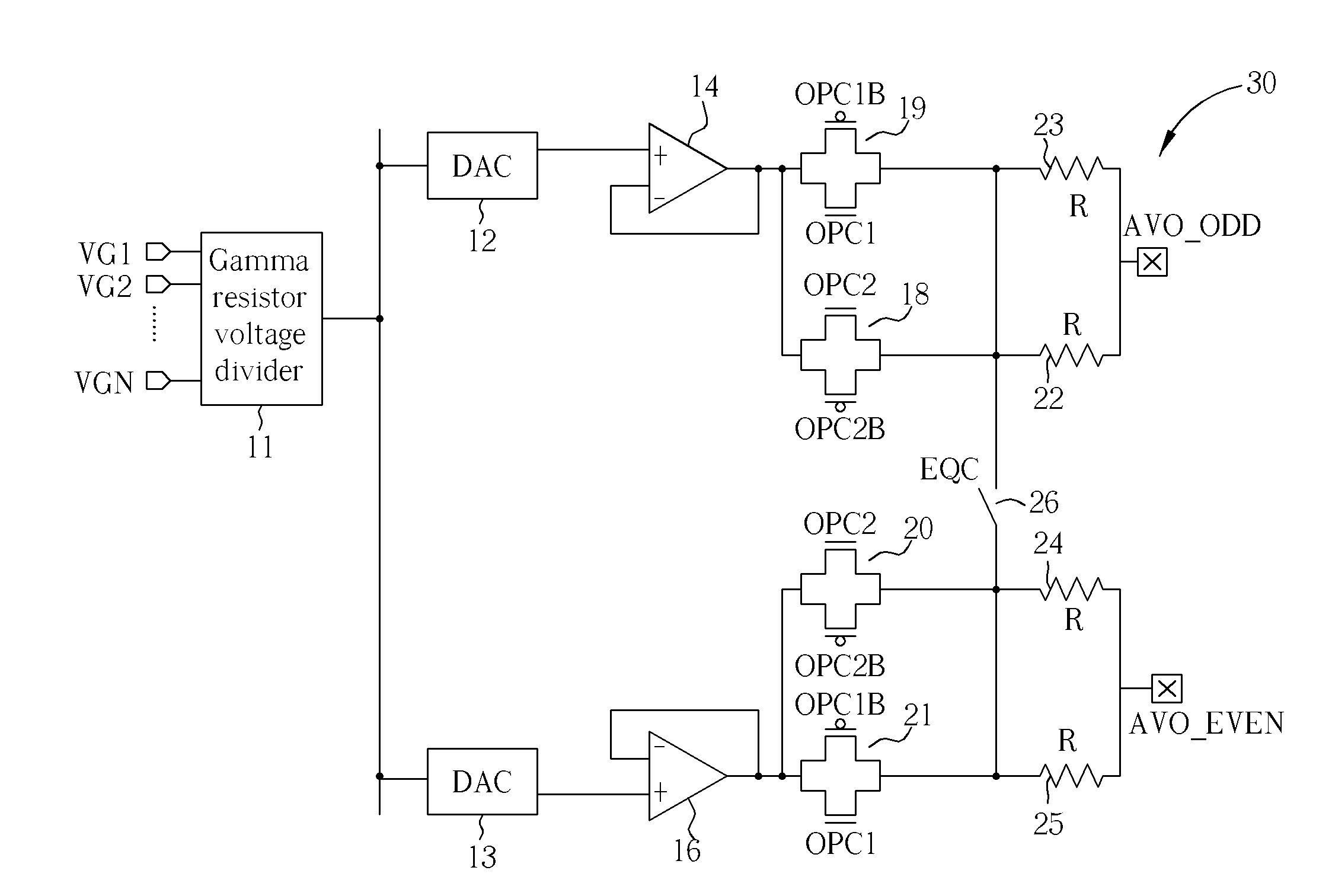
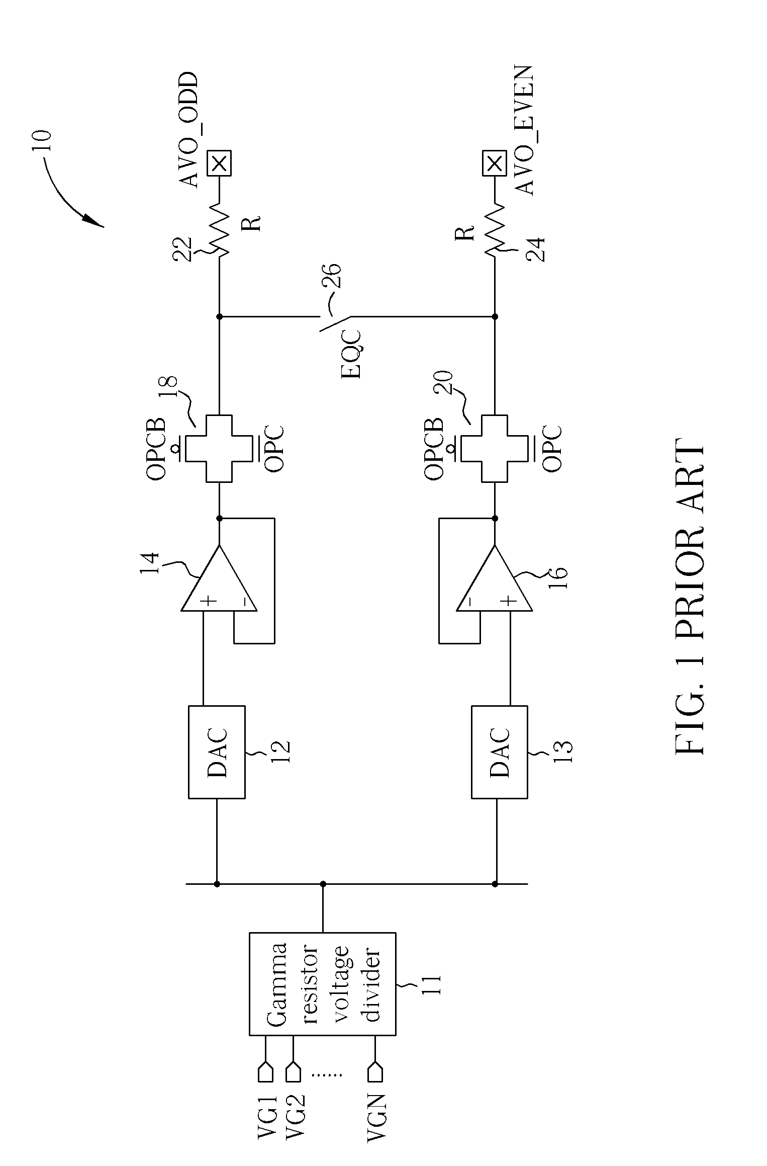
[0026]Please refer to FIG. 3. FIG. 3 is a schematic diagram illustrating a source driver according to a first embodiment of the present invention. The source driver 30 comprises a gamma resistor voltage divider 11, a digital-to-analog converter (DAC) 12, a second DAC 13, a first operational amplifier 14, a second operational amplifier 16, a first output switch 18, a second output switch 20, a third output switch 19, a fourth output switch 21, a first resistor 22, a second resistor 24, a third resistor 23, a fourth resistor 25 and a charge-sharing switch 26.

[0027]Furthermore, the first output switch 18 and the second output switch 20 are controlled by a set of control signals OPC2, OPC2B. The third output switch 19 and the fourth output switch 21 are controlled by a set of control signals OPC1, OPC1B. The charge-sharing switch 26 is controlled by a control signal EQC. The first output switch 18, the second output switch 20, the third output switch 19 and the fourth output switch 21 a...


PUM


Abstract

A source driver includes four output switches, two resistors, and a charge-sharing switch. The first output switch and the first resistor are coupled in series to a first output channel of the source driver. The second output switch and the second resistor are coupled in series to a second output channel of the source driver. The third output switch is coupled in parallel to the first output switch. The fourth output switch is coupled in parallel to the second output switch. The charge-sharing switch is coupled between the first resistor and the second resistor. The third output switch and the fourth output switch are controlled to adjust the resistance of the output current path of the source driver.

Description

BACKGROUND OF THE INVENTION[0001]1. Field of the Invention[0002]The present invention relates to a source driver, and more particularly, to a source driver with high driving ability, high stability and high charge-sharing efficiency.[0003]2. Description of the Prior Art[0004]Please refer to FIG. 1. FIG. 1 is a schematic diagram of a source driver according to the prior art. The source driver 10 comprises a gamma resistor voltage divider 11, a first digital-to-analog converter (DAC) 12, a second DAC 13, a first operational amplifier 14, a second operational amplifier 16, a first output switch 18, a second output switch 20, a first resistor 22, a second resistor 24 and a charge-sharing switch 26. The first output switch 18 and the second output switch 20 are transmission gates respectively controlled by a set of control signals OPC, OPCB, and the charge-sharing switch 26 is controlled by a control signal EQC. The first resistor 22 and the second resistor 24 are electrostatic discharge...

Claims


Application Information

Patent Timeline
IPC IPC(8): H03K3/00
CPCH03K19/0016H03K19/017H03K19/00361H03K19/0019
Inventor CHEN, CHAO-ANSUNG, KUANG-FENG
Owner NOVATEK MICROELECTRONICS CORP
Why Eureka
Try Eureka