
Multi-purpose panels with a modular edge

Inactive Publication Date: 2009-01-15
ACCUFORM CANADA
View PDF13 Cites 16 Cited by
  • Summary
  • Abstract
  • Description
  • Claims
  • Application Information

AI Technical Summary

Benefits of technology

[0017]An apparatus to construct a continuous surface is provided. In one embodiment, a panel is provided having a wafer and a modular joint system that is designed to have a stiffness and weight to satisfy the requirements for a variety of surfaces such as oil rig sites, helicopter pads, temporary roads, housing sites amongst other applications. Each wafer can have at least three sides. An edge having the same or a different profile is attached to one of the sides of the wafer to allow each wafer to be attached to an adjacent wafer. The modular design of the joint system allows for the manufacturer to use and modify existing wafers with different edges to produce a panel that meets the needs of the end user without compromising the strength or rigidity of the joint to facilitate the transfer of load from one panel onto adjacent panels.
[0018]In one embodiment, the wafer and the edge can be changed with little modification to either piece to continually allow for the development of wafers and edges that better fulfill the requirements of industry and the environment or to reuse either the edge or the wafer.
[0019]In another embodiment, the wafer can have a modular design that allows it to be constructed to allow the edges to be interchanged and to allow the selection of different edges on each side of the wafer. As such, a surface can be made using a variety of panels having a variety of edge designs in order to address differences in the requirements of the panel depending on variations on ground conditions or use.
[0020]In another embodiment, the wafer and the edge can have a modular design that allows for the mass production of panel components using highly automated manufacturing techniques, driving the cost of production down and increasing the quality and reliability of the end product.
[0021]In yet another embodiment, allows for the integration of the best possible edge design for any given application and to provide the correct joint system that is appropriate for a given task and demands of the market place.
[0022]In yet another embodiment, the wafer can have a modular design that allows for the integration of the best possible edge design for any given application. There are a wide variety of needs any mat system is required to fulfill, but making the edge and the wafer into separate components that can be interchanged with one another allows the current invention to meet the changing needs of the market place.

Problems solved by technology

First, ongoing damage to such an environmentally sensitive area may prevent the movement of workers, machinery or vehicles over the surface of the area and cause the area to be inaccessible.
Second, the damaged caused by workers, machinery and vehicles may take a decade or more to repair and thus lead to long-term environmental damage to the area.
These roadways used heavy materials that were difficult to handle, put into place and joint together.
As the materials were hard to use these roadways could not be recovered and became permanent structures that were difficult to repair and maintain, and as such were abandoned over time, thus preventing the natural recovery of the environmentally sensitive area.
These prior art systems require the arrangement and assembly of individual boards and are labour intensive to assemble and disassemble.
As such, the joints between the boards do not provide sufficient structure to provide a rigid joint to transfer load between each of the mats.
Further, as the joints are of a fixed configuration, changing the shape or profile of each joint on each mat is not possible.
As with the previous mat systems, the joints are of a fixed configuration that does not provide sufficient structure to provide a rigid joint to transfer load between each of the wafers.
As such, theses prior art systems have panels that fit together in a pre-determined and specific orientation, and do not allow modification to the edges of the panels to facilitate different types of connections or edge profiles.
As with the other prior art systems, the edge once formed for each panel cannot be changed and cannot be modified after the fabrication of the panel.

Method used


Image

  • Multi-purpose panels with a modular edge
  • Multi-purpose panels with a modular edge
  • Multi-purpose panels with a modular edge

Examples


Embodiment Construction

[0046]In the following description, similar features in the drawings have been given identical reference numerals where appropriate. All dimensions described herein are intended solely to illustrate an embodiment. These dimensions are not intended to limit the scope of the wafer described herein, which can depart from these dimensions.

[0047]An embodiment is illustrated and described in context of providing a modular edge system for temporary surface used to distribute the load of workers, equipment and vehicles over a large surface area. However, it is contemplated that the modular edge system may be applied to any surface panel or wafer such as wall panels, ceiling panels, roofing, flooring, walkways or the like.

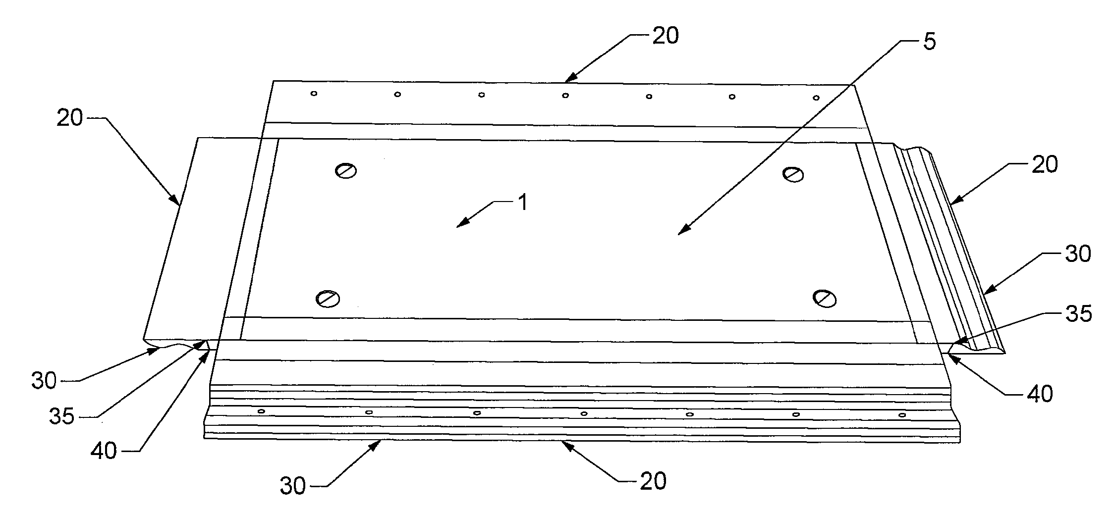
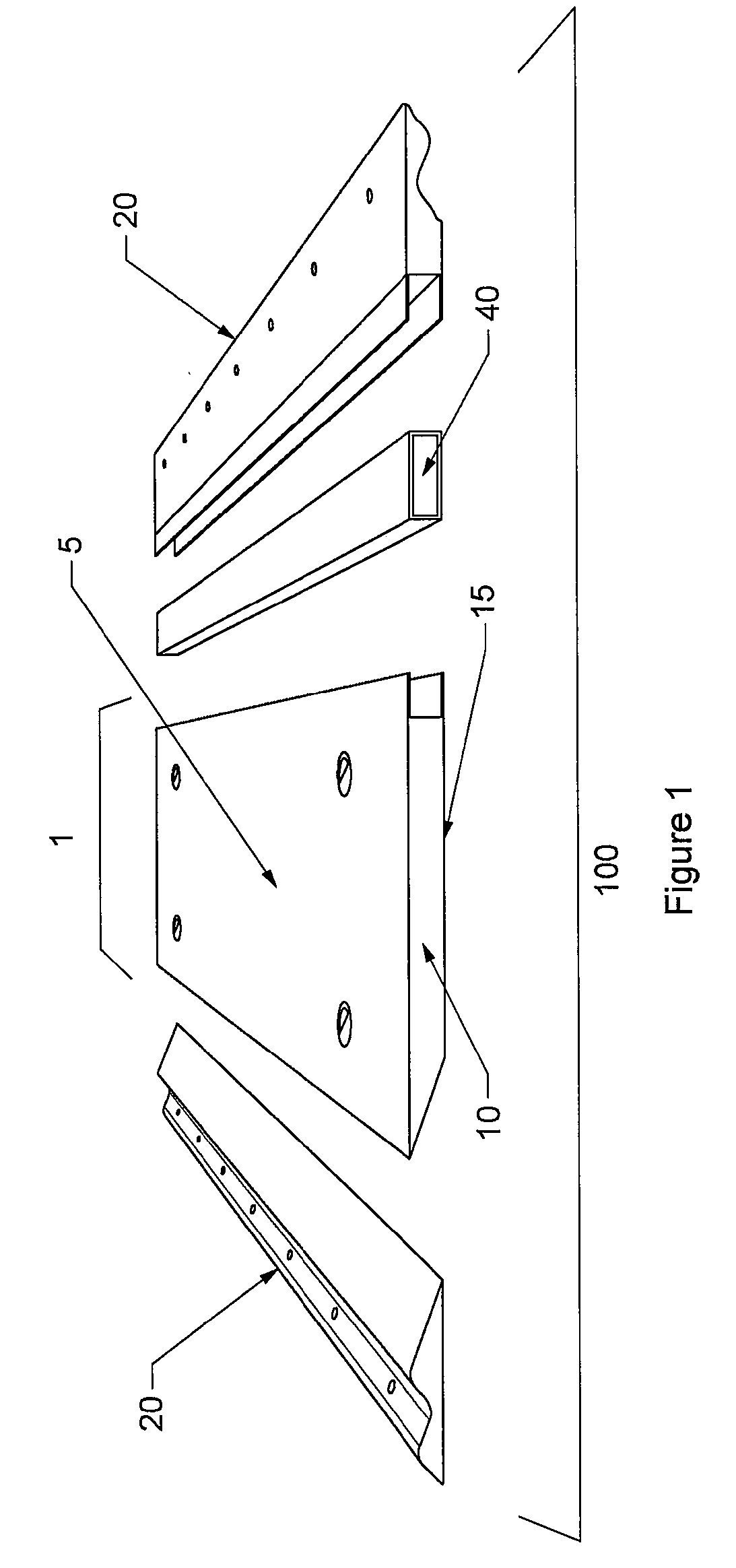
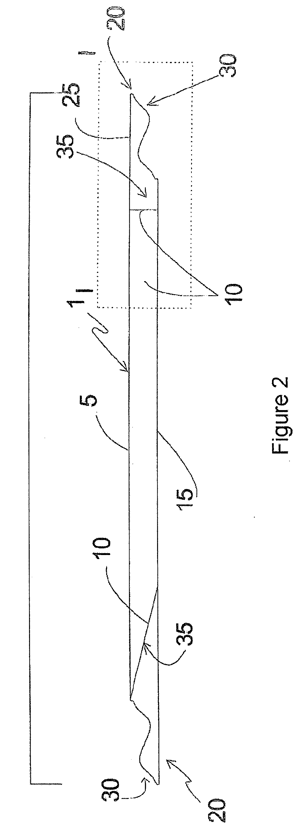
[0048]Referring to FIG. 1 and FIG. 2, there is illustrated a panel 100 according to one embodiment of the present invention having, a wafer 1, an upper wafer skin 5 and an opposing bottom wafer skin 15. Referring to FIG. 3 and FIG. 4, the wafer has at least three sides 10 w...


PUM


Abstract

A panel for use in constructing a mat or a road and method for same is provided. The panel can include a wafer having at least three sides operatively coupled to an edge having a complementary profile for overlapping and attaching to another edge coupled to another wafer. The edge can be attached to the wafer using a scarf joint or a mortise and tenon joint. The complementary profile can include a lap joint, a tapered lap joint, an S-shaped lap joint or a modified lap joint for use with fasteners for attaching two edges together.

Description

CROSS-REFERENCE TO FOREIGN PRIORITY APPLICATION[0001]Priority is claimed under 35 U.S.C. §119 to Canadian Application No. 2,593,600 entitled “Multi-Purpose Panels with a Modular Edge,” filed on Jul. 13, 2007, by Richard Kulhawe and Anthony G. Warren.BACKGROUND OF THE INVENTION[0002]1. Field of the Invention[0003]The present invention relates to multi-purpose panels for constructing a continuous surface and, in particular, panels comprising of wafers having at least one modular edge.[0004]2. Description of the Related Art[0005]Access into wilderness areas for the purposes of natural resource discovery and exploitation requires that heavy equipment traverse areas having sensitive soil types that are easily compressed or damaged by the presence of workers, machinery and vehicles. Some representative examples of such areas are desert, muskeg, tundra, and farmland.[0006]The fact that such environments are sensitive to the damage by compression or erosion caused by workers, machinery and ...

Claims


Application Information

Patent Timeline
IPC IPC(8): E01C5/00E04F13/08
CPCE01C5/00E01C9/08E04F2201/026E04F13/08E04F15/02E01C2201/12E04F15/041E04F15/02194E04F15/06E04F15/082E04F15/105
Inventor KULHAWE, RICHARDWARREN, ANTHONY G.
Owner ACCUFORM CANADA
Learn More