In-line wafer robotic processing system

a robotic processing and wafer technology, applied in the field of systems and methods for wafer processing, can solve the problems of inability to meet the needs of rtp or sao in a continuous processing operation, the cost per square foot is not readily available, and the vacuum or other pressure in the clean room is not readily availabl

Inactive Publication Date: 2009-01-15
WAFERMASTERS
View PDF17 Cites 65 Cited by
  • Summary
  • Abstract
  • Description
  • Claims
  • Application Information

AI Technical Summary

Benefits of technology

[0018]In another embodiment of the present disclosure, a method of processing wafers includes providing a plurality of wafers in a one or more front opening unified pods (FOUPs) at an ambient pressure. The wafers from the FOUPS are placed in one of a plurality of loadlock chambers using a first robot arm. Using a second robot arm in a transport chamber, the wafers are transferred from one of the loadlock chambers to one or more process chambers in succession though a transport chamber that is at a pressure different than the ambient pressure. A process associated with each of the process chambers is performed on the one or more wafers. The wafers are moved from the succession of process chambers to one of the loadlock cooling stations using the second robot arm. The wafers are removed from the loadlock cooling station to one of the plurality of FOUPs using the first robot arm operating at ambient pressure.

Problems solved by technology

One is the cost per square foot, particularly of the floor space within clean rooms.
Unfortunately, an integrated processing environment in which the environment is completely controlled, for example, from the transfer of wafers from a FOUP, to a loadlock chamber, to one or more process and characterization chambers, such as a rapid thermal processing furnace or a stacked wafer annealing oven, characterization chambers, cooling stations, and finally returned to a FOUP at ambient clean room pressure from vacuum or other pressure is not readily available to meet the needs of RTP or SAO in a continuous processing operation.
Robotic handling may currently be limited to transfer handling between only two particular stations, which may result in considerable duplication, footprint increase, and cost to automate each step of handling and processing.
Transfers between wafer storage / handling systems, such as FOUPs and loadlocks may currently be manual, which may result in additional contamination concerns due to human presence in the fabrication process.
Furthermore, current systems may require clean room floor space that results in increased cost in terms of throughput per square-meter of floor space.

Method used


Image

  • In-line wafer robotic processing system
  • In-line wafer robotic processing system
  • In-line wafer robotic processing system

Examples


Embodiment Construction

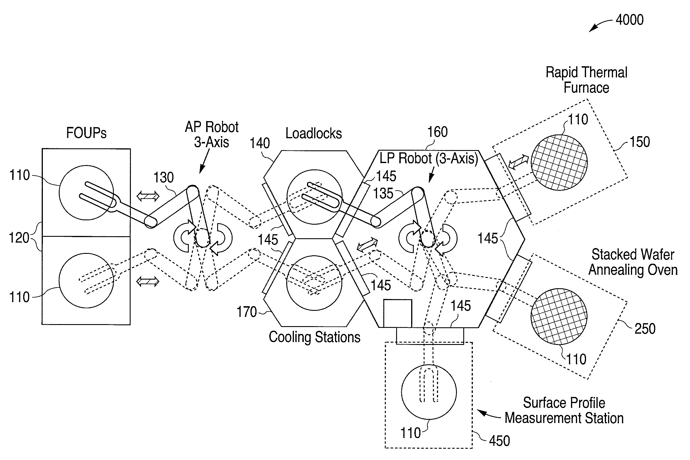
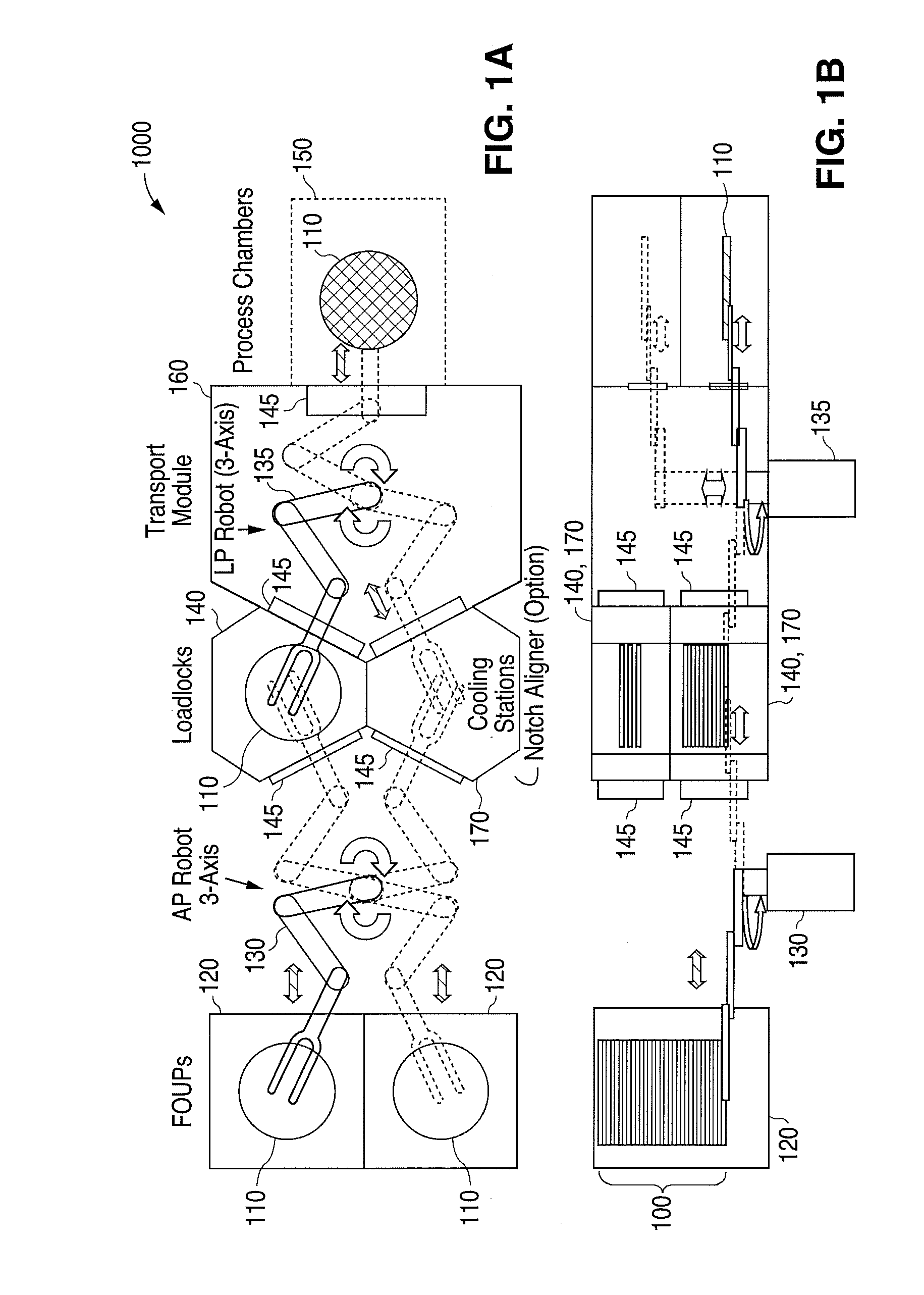
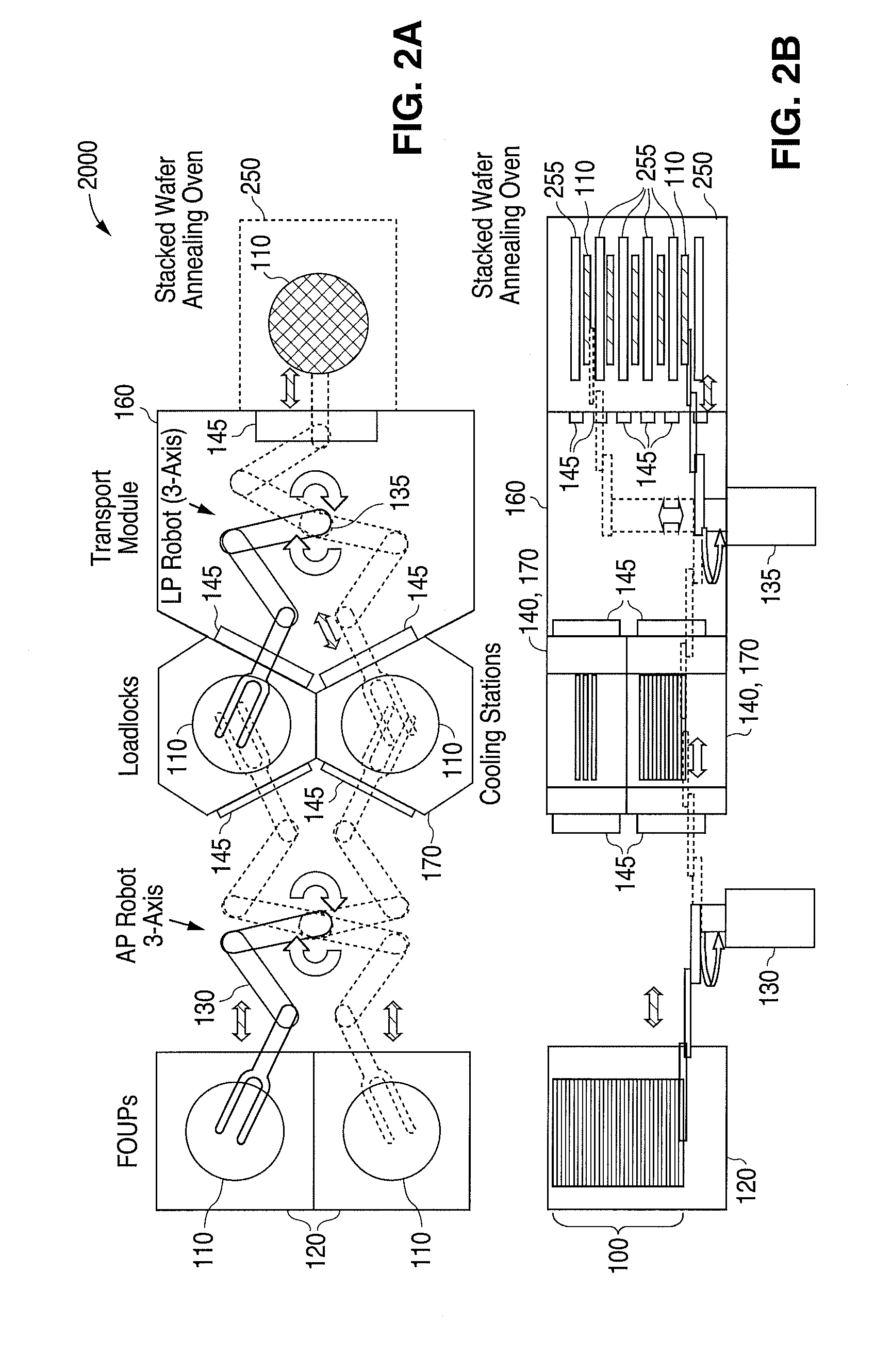
[0029]FIG. 1A is a top view of an in-line single wafer robotic rapid thermal processing furnace system 1000, according to one embodiment of the disclosure. FIG. 1B is a side view of the in-line single wafer robotic rapid thermal processing furnace system 1000, as shown in FIG. 1A. In the embodiment shown in FIGS. 1A and 1B, it is noted that various modules may be positioned vertically as well as horizontally, thereby reducing the footprint of system 1000.

[0030]System 1000 may operate entirely within a clean room, where environmental characteristics including at least particulate filtration, temperature, and humidity are controlled. Vertically stacked sets 100 of horizontally oriented wafers 110 may be obtained from or returned to one or more vertically and / or horizontally positioned front opening unified pods (FOUPs) 120 by a clean room ambient pressure (AP) robot arm 130. The stacking of sets 100 and orientation of wafers 110 is exemplary, and not limiting in accordance with the di...


PUM


Abstract

A system for processing semiconductor wafers, includes a plurality of front opening unified pods (FOUPs), loadlocks for receiving the plurality of wafers, a plurality of process chambers configured to perform processing steps and or measurement steps on the wafers, loadlock cooling stations for receiving the wafers from the processing chambers and a transport chamber interconnecting the loadlocks, cooling chambers and process chambers. A first multi-axis robot transfers wafers between the FOUPs, loadlocks and loadlock cooling stations, at an ambient pressure. A second multi-axis robot tranfers wafers between the loadlocks, process chambers and the loadlock cooling stations, and is adapted to operate in a transport chamber at a pressure that is different from the ambient pressure.

Description

BACKGROUND[0001]1. Field of Invention[0002]This invention generally relates to semiconductor manufacturing methods and, more particularly, to systems and methods for wafer processing using multiple process chambers accessed through a plurality of load locks and cooling chambers by multiple robots.[0003]2. Related Art[0004]In the semiconductor industry, to continue to make advancements in the development of semiconductor devices, especially semiconductor devices of decreased dimensions, new processing and manufacturing techniques have been developed.[0005]The semiconductor industry continues a predictable trend toward higher densities of the features within integrated circuits. From the 10-micron range in 1970, feature dimensions of 0.13 microns to 65 mn are now common. These extremely high densities have driven the need for extremely clean processes within semiconductor fabrication facilities. The concern for contamination has been one force driving the automation of processes and t...

Claims


Application Information

Patent Timeline
Patent Type & Authority Applications(United States)
IPC IPC(8): H01L21/677
CPCH01L21/67201H01L21/67288H01L21/67766H01L21/67742H01L21/67294
Inventor YOO, WOO SIK
Owner WAFERMASTERS
Why Eureka
Try Eureka