Wind turbine blade tip vortex breakers

a technology of blade tip and blade blade, which is applied in the direction of liquid fuel engines, vessel construction, marine propulsion, etc., can solve the problems of reducing turbine power and unadjustable blade tip configuration

Inactive Publication Date: 2009-01-15
GENERAL ELECTRIC CO
View PDF14 Cites 69 Cited by
  • Summary
  • Abstract
  • Description
  • Claims
  • Application Information

AI Technical Summary

Problems solved by technology

However, these and other conventional approaches to blade tip configuration do not adequately address the problems of aerodynamic efficiency and wing tip noise because they can actually increase blade drag which correspondingly reduces turbine power.

Method used


Image

  • Wind turbine blade tip vortex breakers
  • Wind turbine blade tip vortex breakers
  • Wind turbine blade tip vortex breakers

Examples


Embodiment Construction

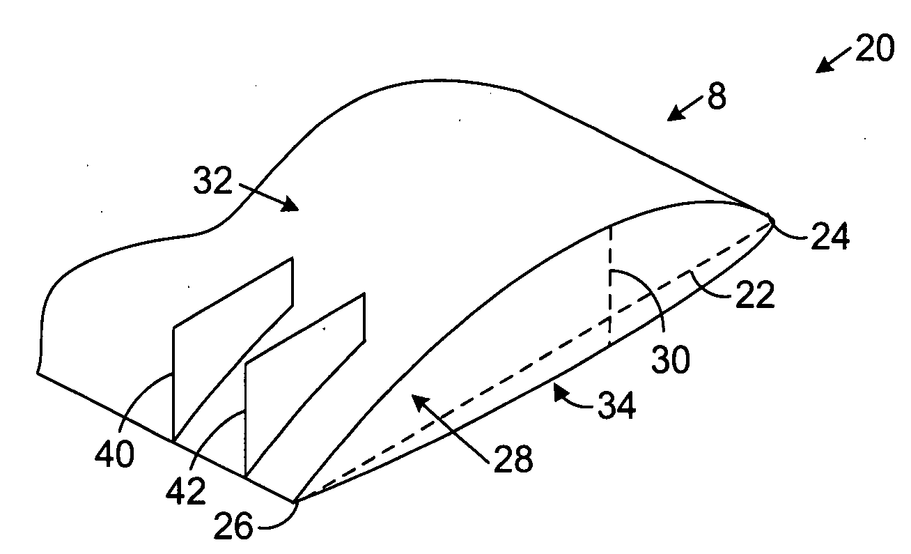
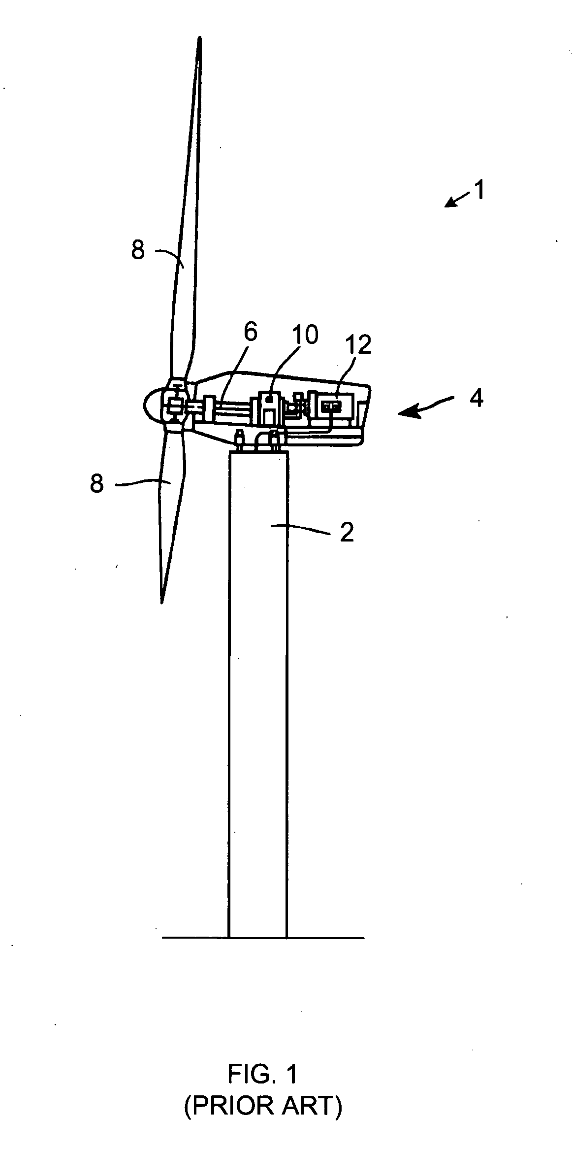
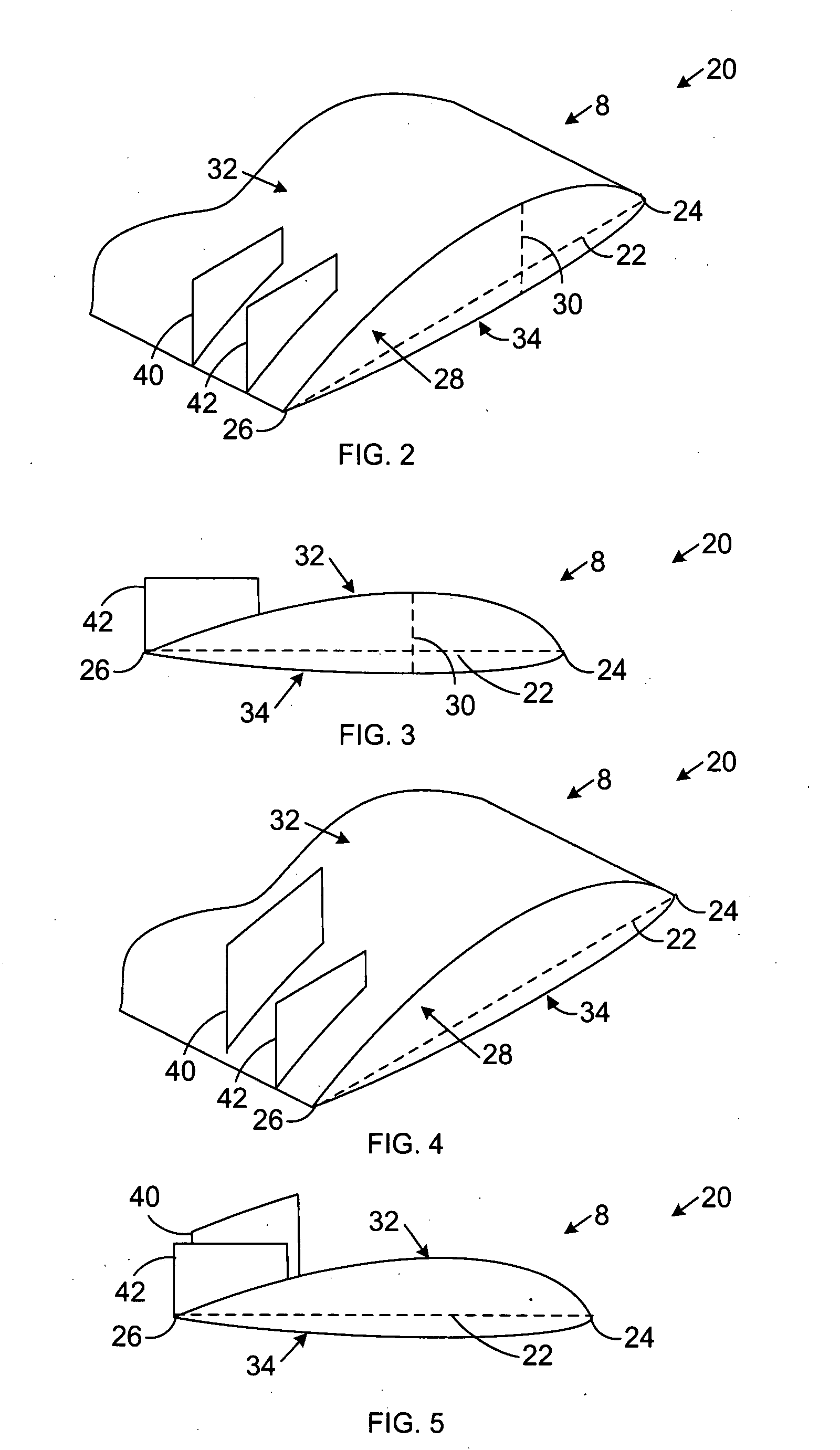
[0022]FIG. 2 is an orthographic view of an enlarged tip portion of a wind turbine blade including one example of a tip vortex breaker system 20. FIG. 3 is an end view of the wind turbine blade vortex breaker system 20 illustrated in FIG. 2. In FIGS. 2 and 3, the tip vortex breaker system 20 is illustrated in connection with the blade 8 shown in FIG. 1. However, any other wind turbine blade may also be used. For example, the vortex breaker system 20 may be used with blades having other planforms, cambers, thicknesses, aspect ratios, and / or tip geometries in addition to the ones illustrated in the figures here.

[0023]In FIGS. 2 and 3, the dashed line represents a tip chord line 22 that extends from the leading edge 24 to the trailing edge 26 of the turbine blade 8. Although the length of this chord line 22, or chord, is illustrated in these figures as being constant for the span of the blade 8 from the root (not show) to the tip 28, the chord may vary along the span of the blade. The m...


PUM


Abstract

A wind turbine includes a tower supporting a drive train with a rotor, at least one blade extending radially from the rotor; and a plurality of substantially flat flaps extending substantially perpendicular from a suction surface of the blade and along different chord lines near a tip of the blade for capturing and directing tip vortices toward a trailing edge of the blade.

Description

BACKGROUND OF THE INVENTION[0001]1. Technical Field[0002]The subject matter described here generally relates to fluid reaction surfaces with specific blade structures, and, more particularly, to wind turbines having vortex breakers near the tip of the blades.[0003]2. Related Art[0004]A wind turbine is a machine for converting the kinetic energy in wind into mechanical energy. If the mechanical energy is used directly by the machinery, such as to pump water or to grind wheat, then the wind turbine may be referred to as a windmill. Similarly, if the mechanical energy is converted to electricity, then the machine may also be referred to as a wind generator or wind power plant.[0005]Wind turbines use an airfoil in the form of a blade to generate lift and capture momentum from moving air that is them imparted to a rotor. The blade is typically secured to a rotor at its root end, and extends radially to free, tip end. The front, or leading edge, of the blade connects the forward-most poin...

Claims


Application Information

Patent Timeline
Patent Type & Authority Applications(United States)
IPC IPC(8): F03D11/02
CPCF03D1/0675Y02E10/721F05B2240/32F05B2240/121Y02E10/72F05B2240/3062
Inventor PARSANIA, NISHANTSTANDISH, KEVIN
Owner GENERAL ELECTRIC CO
Why Eureka
Try Eureka