

Methods For Forming Contacts For Dual Stress Liner CMOS Semiconductor Devices
- Summary
- Abstract
- Description
- Claims
- Application Information
AI Technical Summary
Benefits of technology
Problems solved by technology
Method used
Image

Examples
Embodiment Construction
[0020]Exemplary embodiments of the invention will now be described more fully with reference to the schematic illustrations in the accompanying drawings in which it is to be understood that the thickness and dimensions of the layers and regions are exaggerated for clarity. It is to foe further understood that when a layer is described as being “on” or “over” another layer or substrate, such layer may be directly on the other layer or substrate, or intervening layers may also be present. Moreover, similar reference numerals that are used throughout the drawings are used to denote elements that are the same or similar or having the same or similar functions.
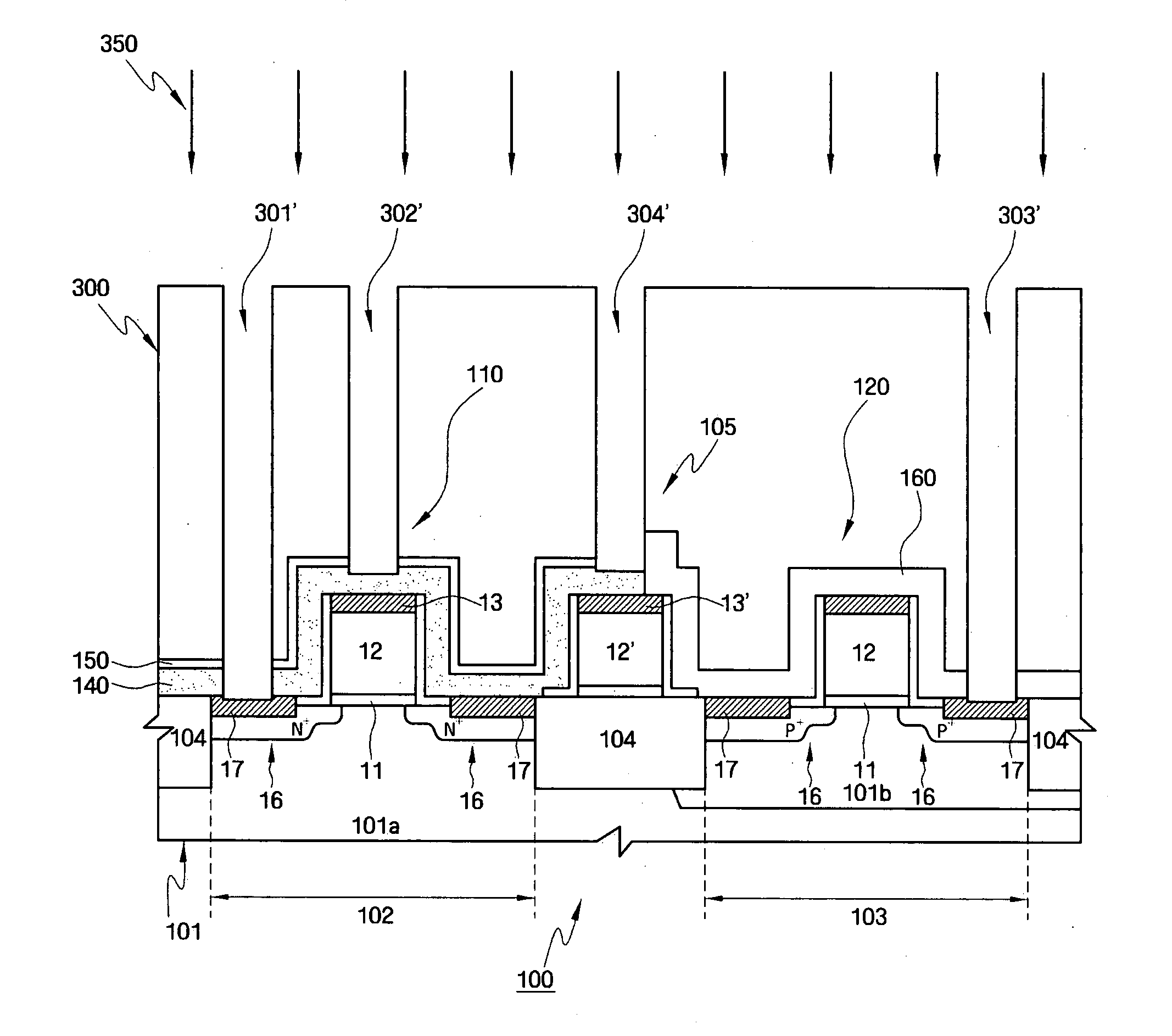
[0021]FIGS. 3A˜3F schematically illustrate a method for forming via contacts in dual stress liner CMOS devices having overlapped stress liners according to an exemplary embodiment of the invention. For purposes of illustration, FIGS. 3A˜3F depict an exemplary method for forming via contacts for a dual stress liner CMOS device as il...
PUM
 Abstract
Description
Claims
Application Information