

Endoscopic surgical tool
a surgical tool and endoscope technology, applied in the field of endoscope surgical tools, can solve problems such as wire breaking, and achieve the effect of safe operation
- Summary
- Abstract
- Description
- Claims
- Application Information
AI Technical Summary
Benefits of technology
Problems solved by technology
Method used
Image

Examples
first embodiment
[0035]the present invention of the endoscopic treatment tool will be explained with reference to FIGS. 1 to 3.
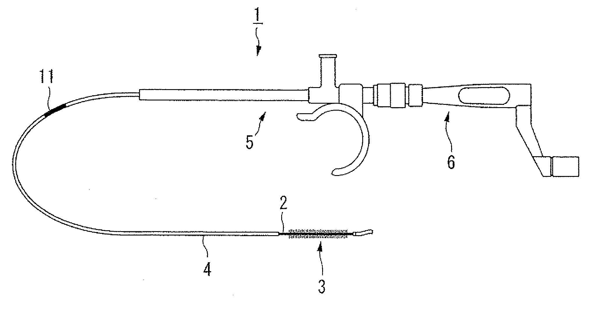
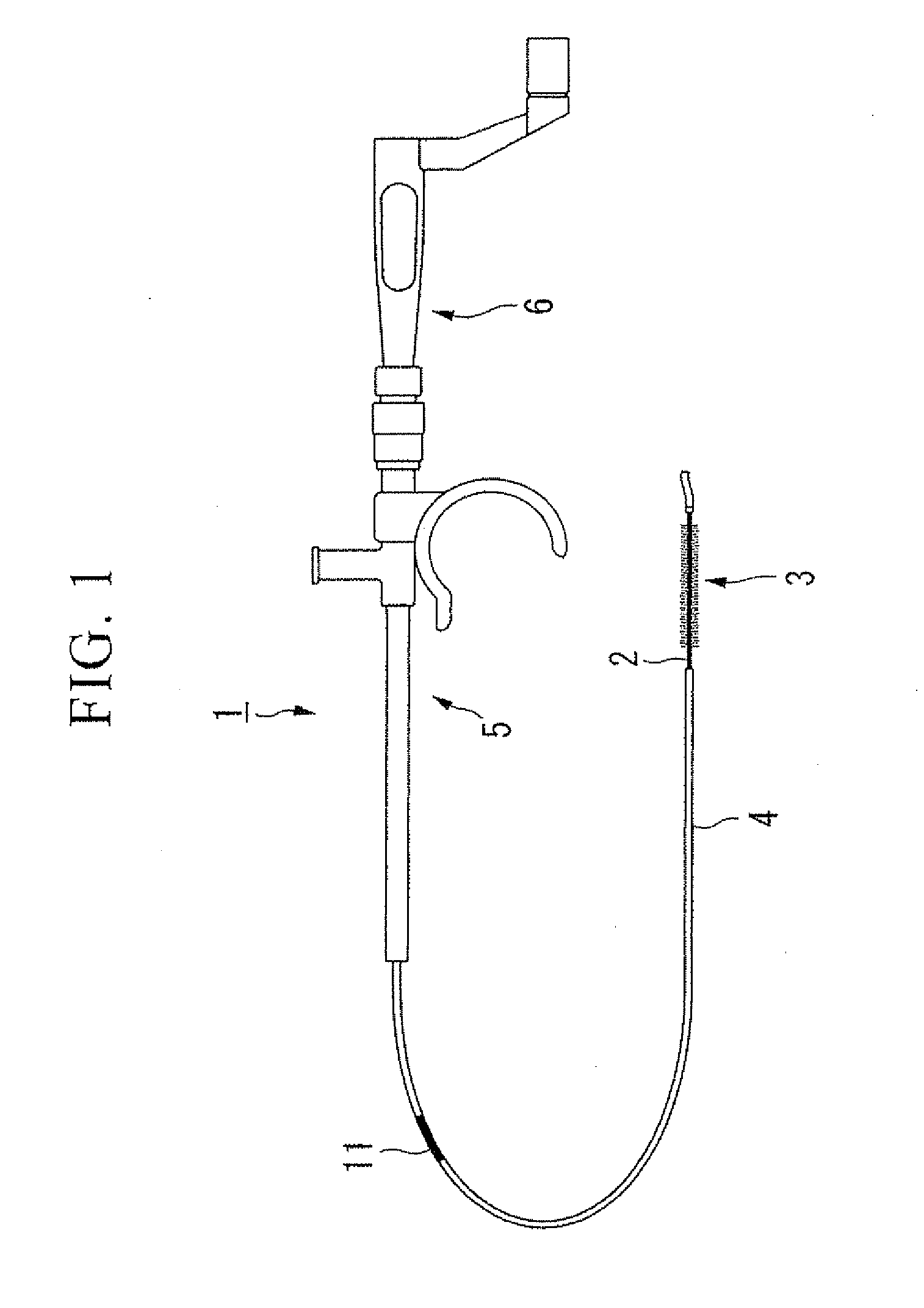
[0036]FIG. 1 is an overall structure of an endoscopic treatment tool 1 of the present embodiment. As shown in FIG. 1, the endoscopic treatment tool 1 includes a wire 2, a surgical section 3 disposed at a distal end of the wire 2, a sheath 4 in which the wire 2 is inserted through, a main body 5 in which the sheath 4 is fixed and an operator section 6 which is disposed at a proximal side of the main body 5.
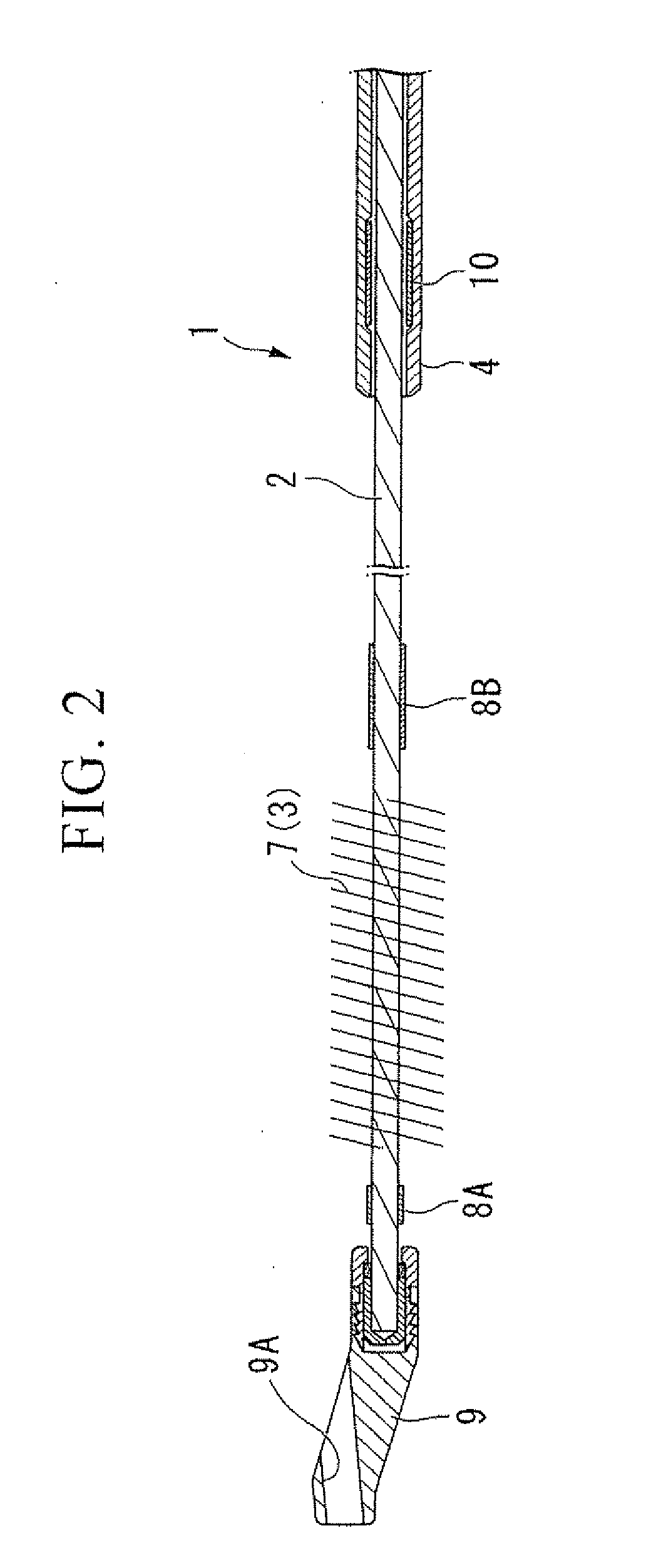
[0037]FIG. 2 is an enlarged diagram in the vicinity of the distal end of the wire 2 (a first end portion). The wire 2 is formed by twisting two metal wires together. A plurality of synthetic fibers 7 is inserted in the metal wires at the distal end portions of the wire 2 so as to form a brush-shaped surgical section 3.
[0038]Brush markers 8A and 8B made of stainless steel are disposed at both the front and rear portions of the surgical section 3 by caulking, respectively, so...
third embodiment
[0071]Next, the present invention will be explained with reference to FIGS. 10 and 11. The endoscopic treatment tool 41 of the present embodiment differs from the endoscopic treatment tool 1 described above in that a pipe of an operator section and a handle are held by friction force.
[0072]In the following description, components that are the same as the first embodiment shall be provided with the same numeric symbols and redundant descriptions shall be omitted.
[0073]FIG. 10 is an enlarged cross-sectional diagram of an operator section 42 of the endoscopic treatment tool 41. As shown in FIG. 10, the pipe 43 is inserted into an insertion hole 44B disposed at an end portion 44A of a handle 44, the insertion hole 44B has substantially the same inside diameter as an outside diameter of the pipe 33.
[0074]A ring-shaped groove 44C is disposed along a periphery direction at a predetermined position of the insertion hole 44B. A holding member 45 such as an O-ring made of an elastic material ...
fifth embodiment
[0086]Next, the present invention is described with reference to FIGS. 14 to 16C. An endoscopic treatment tool 61 of the present embodiment differs from the endoscopic treatment tool 1 described above in that a rear end of a wire is protruded outside of a pipe.
[0087]In the following description, components that are the same as the first embodiment shall be provided with the same numeric symbols and redundant descriptions shall be omitted.
[0088]FIG. 14 is an overall view of the endoscopic treatment tool 61. In the endoscopic treatment tool 61, the rear end of the wire 2 is protruded from an operator section 62.
[0089]FIG. 15 is an enlarged view that includes a cross-section of the operator section 62. A pipe 63 is fixed on a handle 64 by welding. A notch 63A is disposed at a predetermined position on the outer surface of the pipe 63, and the rear end 2A of the wire 2 is protruded out to the pipe 63 from the notch 63A by being bent substantially 90 degrees.
[0090]A movement of an endosc...
PUM
 Abstract
Description
Claims
Application Information