Automatically driving force releasing type one way rotation driving instrument

a technology of driving instrument and automatic release, which is applied in the direction of foot-driven lever, wheelchair/patient conveyance, interlocking clutch, etc., can solve the problems of complicated and expensive drive instruments, load applied to the upper limbs, and patients' shoulders may be injured, so as to reduce the friction resistance between the rope member and the input shaft and fine adjustment of position

Inactive Publication Date: 2009-01-22
JAPAN LABOUR HEALTH & WELFARE ORG
View PDF13 Cites 10 Cited by
  • Summary
  • Abstract
  • Description
  • Claims
  • Application Information

AI Technical Summary

Benefits of technology

[0018]With this arrangement, the rope member which is wound around the input shaft of the one way clutch, and the pedal support frame which pivots when a patient steps on a pedal, are connected to each other, and when the pedal is stepped on, the pedal support frame pivots forwardly and the rope member is pulled in a direction away from the input shaft. Since the other end of the rope member which is wound around the input shaft is secured to the frame via the tension spring so that the friction resistance...

Problems solved by technology

When the wheelchair is driven by operating the hand rims with upper limbs, a large load is applied to the upper limbs so that it has been reported that shoulders of patients may be injured.
The conventional rotation driving instrument for driving two rear wheels via a crank mechanism by seating on the saddle and stepping on the pedals has noted only the forward driving so that when the device starts moving forwardly, the pedals continue moving even after patient's feet separate from the pedals, which is dangerous.
In the wheelchair having a drive sys...

Method used


Image

  • Automatically driving force releasing type one way rotation driving instrument
  • Automatically driving force releasing type one way rotation driving instrument
  • Automatically driving force releasing type one way rotation driving instrument

Examples


Embodiment Construction

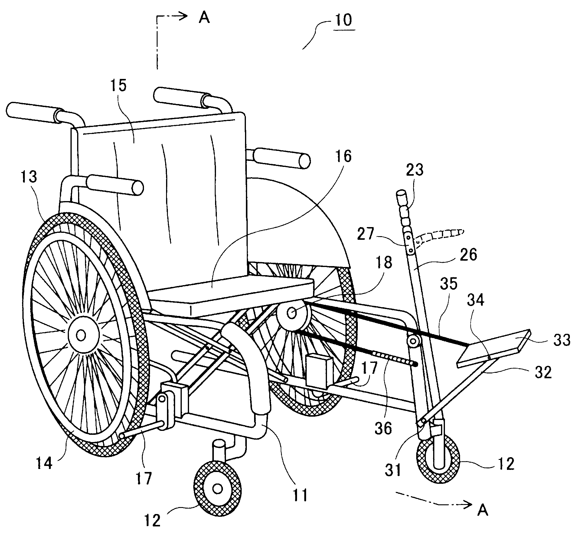
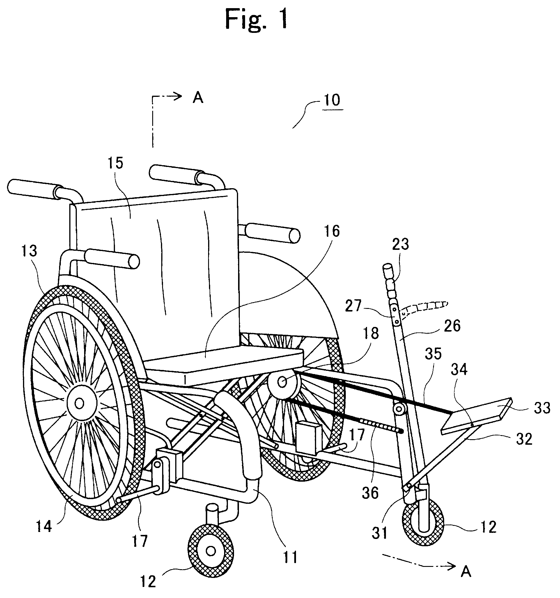
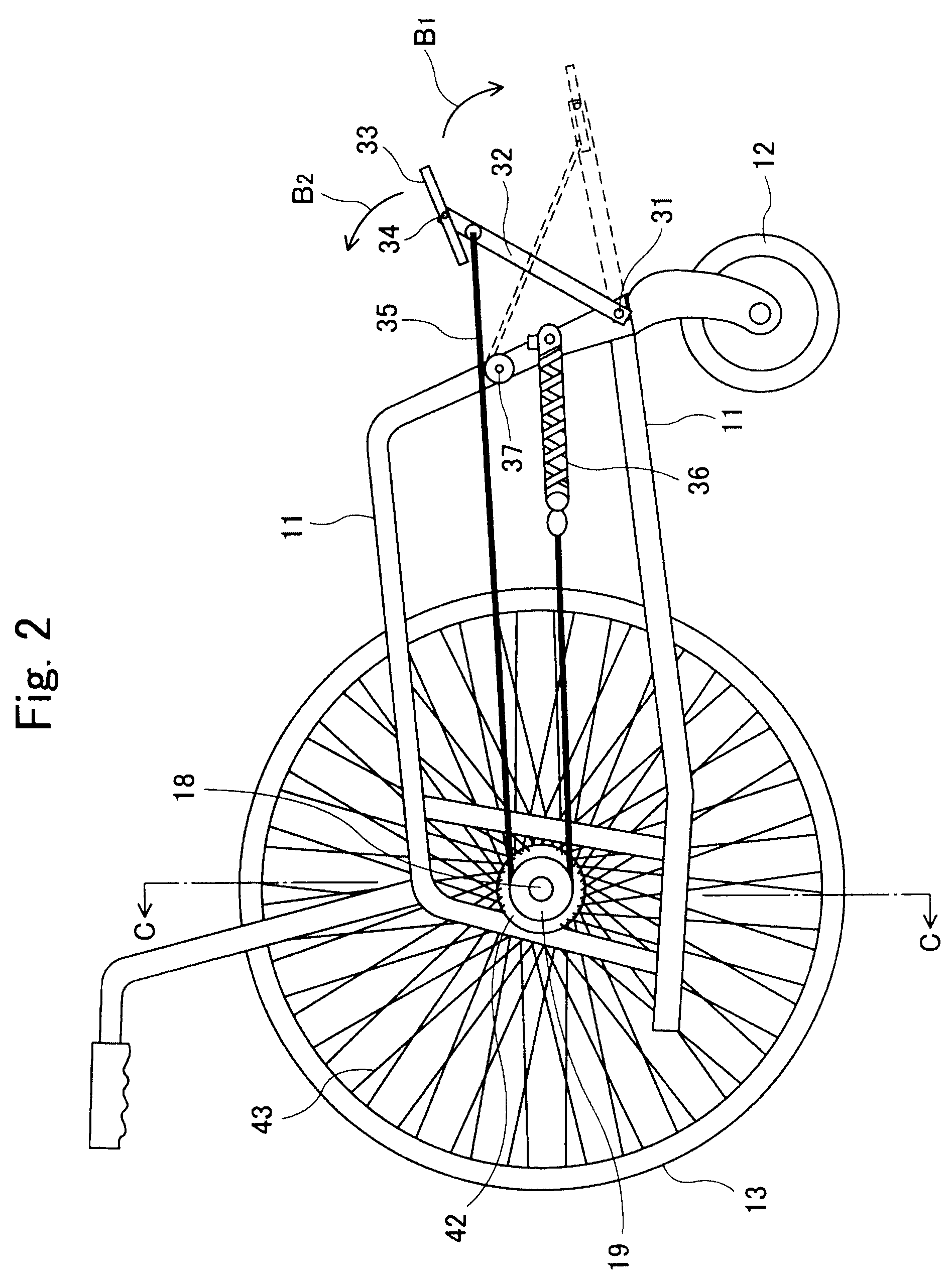
[0024]Hereinafter, one embodiment of the present invention will be explained with reference to FIGS. 1 through 3.

[0025]FIG. 1 is a perspective view of a wheelchair provided with an automatically driving force releasing type one way rotation driving instrument in accordance with the present invention. A wheelchair 10 has a frame 11 composed of pipes, similarly to normal wheelchairs, and front wheels are composed of casters 12, each having a smaller diameter, whereas rear wheels are composed of drive wheels 13, each having a larger diameter. A hand rim 14 is directly connected to the drive wheel 13, and by operating left and right hand rims 14, the left and right drive wheels 13 are driven to rotate such that the wheelchair 10 can move forwardly and backwardly and turn leftwardly and rightwardly. A canvas is stretched between a left side portion and a right side portion of the frame 11 to define a seat back 15 and a seat 16. And a brake device 17 is attached to a lower part of the rig...


PUM


Abstract

An automatically driving force releasing type one way rotation driving instrument for a wheelchair includes a one way clutch 50 for transmitting a driving force only when an output shaft 50b is connected to a drive wheel 13 of a wheelchair 10 and an input shaft 50a is driven in the direction in which the wheelchair 10 is moved forwardly, a rope member 35 which is wound around at least one part of an outer periphery of the input shaft 50a of the one way clutch 50, pulling means 32 and 33 for pulling one end of the rope member 35 with respect to a central part thereof in a direction away from the input shaft 50a, and restraining means 36 for restraining the other end of the rope member 35 with respect to the central part thereof from moving in the direction of the input shaft 50a due to pulling with the pulling means 32 and 33.

Description

CROSS-REFERENCE TO RELATED APPLICATION[0001]This application is related to and claims priority from Japanese patent application No. 2007-189577, filed on Jul. 20, 2007, incorporated herein by reference.BACKGROUND OF THE INVENTION[0002]1. Field of the Invention[0003]The present invention relates to a one way rotation driving instrument for automatically releasing a driving force of a moving body and a wheelchair, and, more particularly, to an automatically driving force releasing type one way rotation driving instrument which can be driven with not only upper limbs but also lower limbs.[0004]2. Description of Related Art[0005]Generally, a wheelchair has the arrangement that rear wheels are drive wheels with larger diameters, front wheels are casters with smaller diameters, and hand rims are directly connected to the rear drive wheels so as to be driven by patient's hands. And the rear wheels are provided with a brake device. When the wheelchair is driven by operating the hand rims wi...

Claims


Application Information

Patent Timeline
IPC IPC(8): A61G5/02A61G5/10B62M1/04B62M9/00B62B5/00B62M1/24
CPCA61G5/023B62M1/28A61G2005/1051A61G5/024A61G5/1051
Inventor GENDA, EIICHIOHTA, KAZUSHIGE
Owner JAPAN LABOUR HEALTH & WELFARE ORG
Why Eureka
Try Eureka