
Cell controller

a cell controller and controller technology, applied in the direction of battery/fuel cell control arrangement, hybrid vehicles, instruments, etc., can solve the problems of large bypass current and difficulty in normal soc adjustment of unit cells, and achieve the effect of enhancing the safety of the cell controller

Active Publication Date: 2009-01-22
HITACHI ASTEMO LTD
View PDF3 Cites 16 Cited by
  • Summary
  • Abstract
  • Description
  • Claims
  • Application Information

AI Technical Summary

Benefits of technology

[0006]In view of the above circumstances, an object of the present invention is to provide a cell controller which is capable of ensuring high safety even when a short occurs among voltage detecting lines without causing increased costs.
[0008]In the present invention, the resistors for SOC adjustment are inserted in series to the voltage detecting lines and the positive electrode and negative electrode of each of the unit cells are connected through each of the voltage detecting lines to the control circuit including the unit cell voltage detecting section, the switching elements or a like. Accordingly, currents flowing due to a short among the voltage detecting lines are limited and safety of the cell controller can be enhanced and, further, the resistors provided originally for SOC adjustment of each of unit cells are used also for a safety measure, thus preventing an increase in costs. In particular, in a configuration employed in the present invention, that the unit cell voltage detecting section, switching elements, and control section out of the SOC control section are housed in an integrated circuit, voltage detecting terminals used for connection of the unit cells to the unit cell voltage detecting section and conducting terminals used for connection of a drain and / or source of the switching element including FETs to the resistors for SOC adjustment are used commonly to reduce the number of the terminals, thereby enabling the reduction of costs for the integrated circuit.
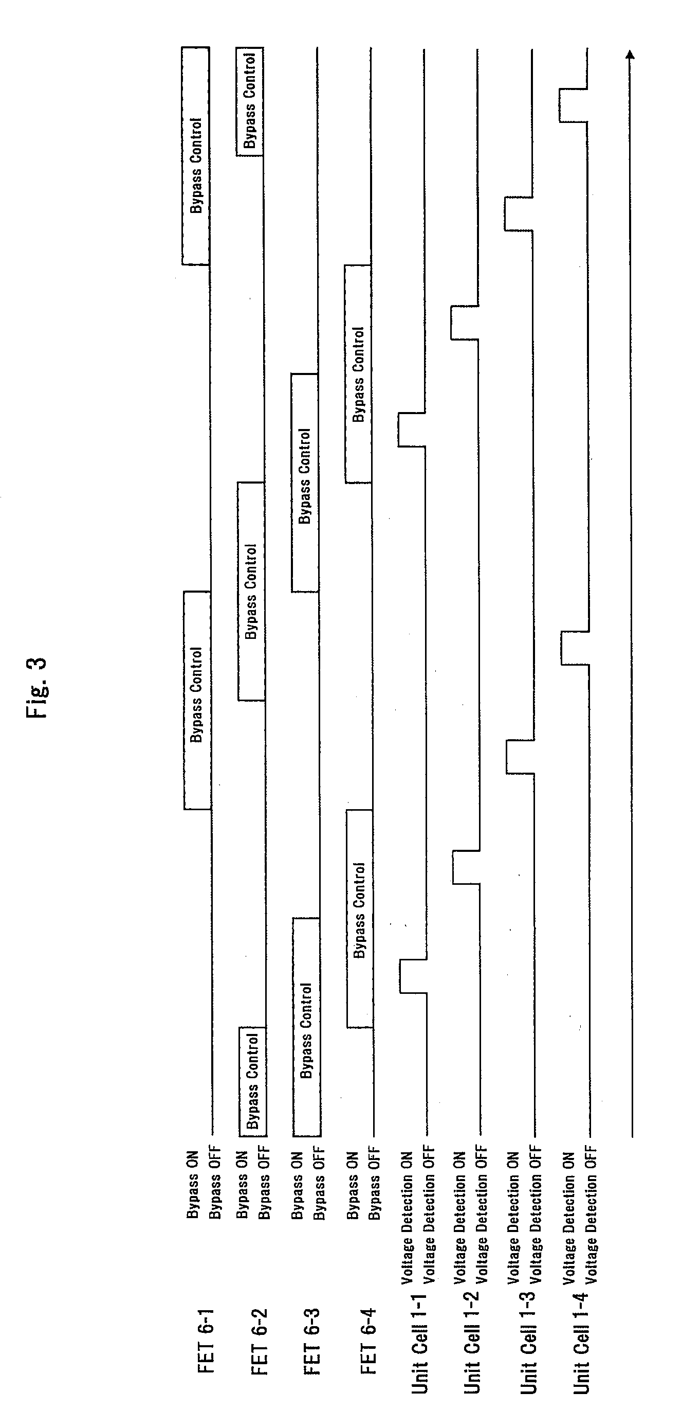
[0009]In the embodiment of the present invention, in a case that, when a unit cell voltage is detected by the unit cell voltage detecting section, the control unit lets each of switching elements corresponding to each of unit cells whose voltage is to be detected and to each of unit cells disposed at higher and lower sides of the each of the unit cells whose voltage is to be detected enter an OFF state, no bypass currents flow at the time of detecting a voltage of each of the unit cells and no voltage drop caused by the resistors of SOC adjustment occurs, which enables the exact measurement of each of the unit cells. Further, when a configuration is employed that the control unit exercises control so that the unit cells whose voltage are to be detected are switched at every predetermined time, the bypass discharging by the resistors for SOC adjustment is stopped only at a time of detecting a voltage of each of the unit cells by using a simple circuit, for example, an oscillating circuit to detect a voltage of each of the unit cells. Furthermore, when a configuration is employed that the control section exercises control so that SOC adjustment is not performed simultaneously among unit cells adjacently disposed at higher and lower sides of each of unit cells constituting the battery group, normal conduction of the bypass current can be achieved. That is, if bypass discharging of unit cells adjacently disposed is performed at the same time, since no currents flow through the resistors for SOC adjustment connected to the voltage detecting lines commonly connected and no voltage drop occurs, resulting in the flow of bypass currents being larger than assumed, thus making it difficult to perform normal SOC adjustment of unit cells. In this configuration, in order to simplify the control, the control section may exercise control so that the unit cells to be adjusted are switched, at every predetermined time, between odd-numbered unit cells and even-numbered unit cells enumerated from a highest or lowest cell constituting the battery group. As described above, it is preferable that the unit cell voltage detecting section, switching elements, and control section making up the SOC adjusting section are housed in an integrated circuit. In a configuration of the present invention, all or part of the resistors is preferably located near the unit cells making up the battery group. The resistors except the resistors connected to a positive electrode of a highest unit cell and a negative electrode of a lowest unit cell out of the unit cells making up the battery group may be disposed near the unit cells constituting the battery group. Moreover, it is preferable that the cell controller further comprises capacitors connected in parallel through the resistors to each of unit cells making up the battery group, and the resistors and the capacitors function as a RC filter. The cell controller can suitably control a battery group operating as a power source for a hybrid electric vehicle.
[0010]According to the present invention, effects can be obtained that since the resistors for SOC adjustment are inserted in series into the voltage detecting lines and the positive electrode and negative electrode of each of the unit cells are connected through each of the voltage detecting lines to the control circuit including the unit cell voltage detecting section, the switching elements or a like, and since currents flowing due to a short among the voltage detecting lines are limited and safety of the cell controller can be enhanced, the resistors provided originally for SOC adjustment of each of unit cells are used also as a safety measure, thus preventing an increase in costs.

Problems solved by technology

That is, if bypass discharging of unit cells adjacently disposed is performed at the same time, since no currents flow through the resistors for SOC adjustment connected to the voltage detecting lines commonly connected and no voltage drop occurs, resulting in the flow of bypass currents being larger than assumed, thus making it difficult to perform normal SOC adjustment of unit cells.

Method used


Image

  • Cell controller
  • Cell controller
  • Cell controller

Examples


Embodiment Construction

[0015]Next, an embodiment of the cell controller of the present invention is described by referring to drawings.

[0016](Constitution)

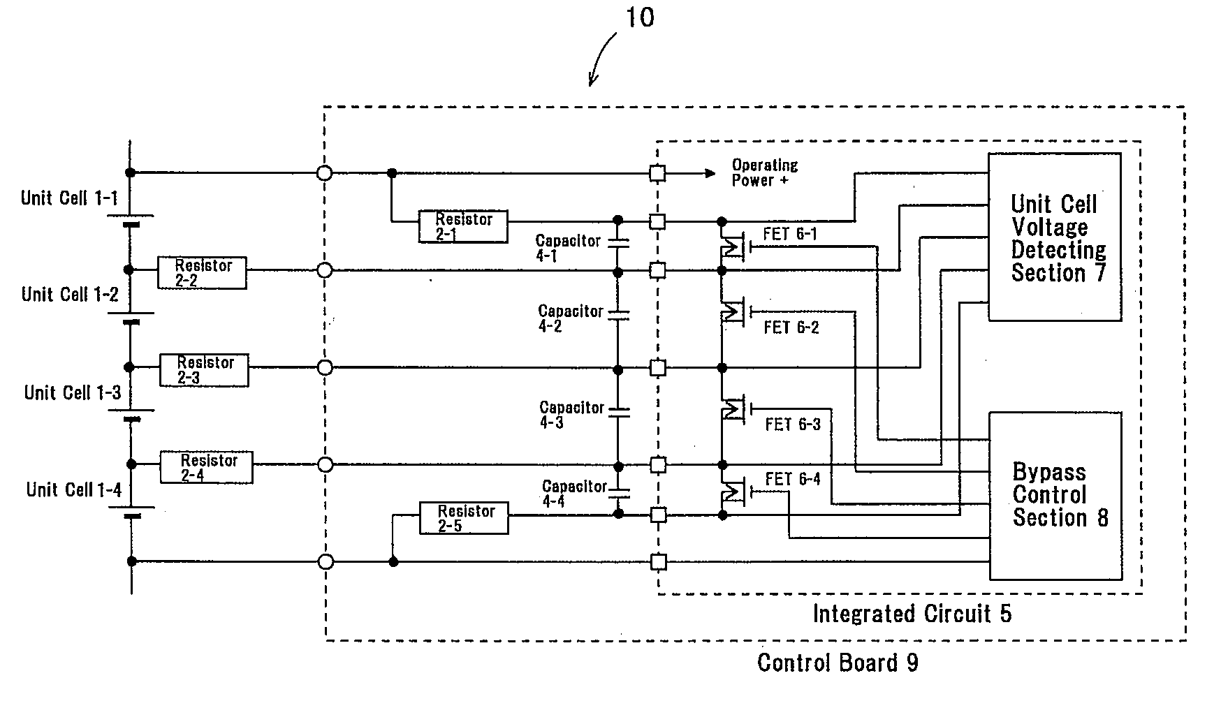
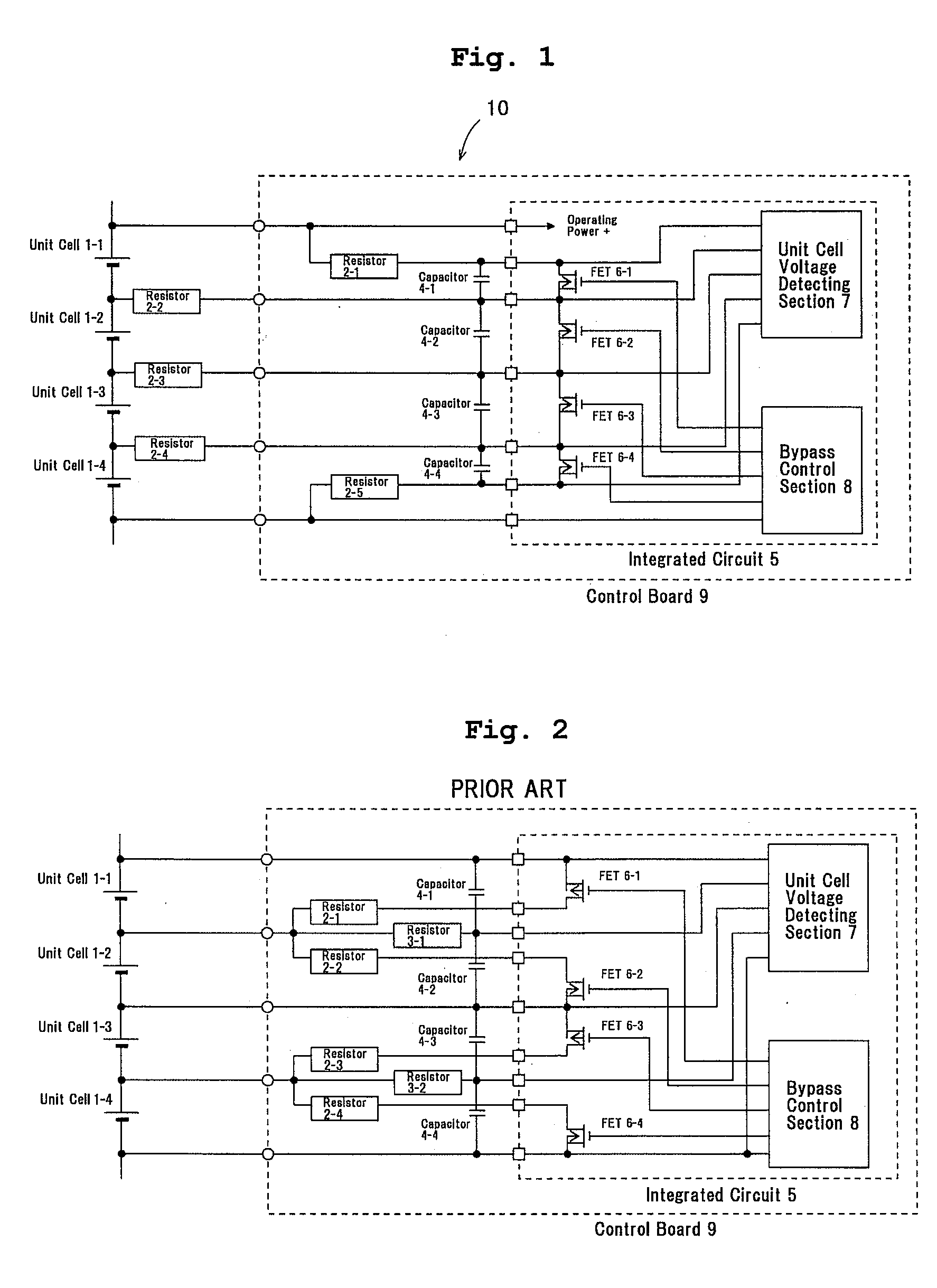
[0017]As shown in FIG. 1, the cell controller 10 includes a unit cell voltage detecting section 7 to detect a voltage of each of unit cells 1-1, 1-2, 1-3, and 1-4 making up a battery group through each of voltage detecting lines and a SOC adjusting circuit (SOC adjusting section)for adjusting a SOC of each of the unit cells 1 having SOC adjusting resistors 2-1, 2-2, 2-3, 2-4, and 2-5, FETs 6-1, 6-2, 6-3, and 6-4 serving as a switching element to supply a bypass current to the SOC adjusting resistors 2, and a bypass control section 8 serving as a control unit to exercise on / off control on the FETs 6.

[0018]The unit cell voltage detecting section 7, bypass control section 8, and FETs 6 (SOC adjusting circuit excluding the SOC adjusting resisters 2) are housed in the integrated circuit 5. The integrated circuit 5 is mounted in the control board 9 making up ...


PUM


Abstract

A cell controller capable of ensuring high safety even when a short occurs among voltage detecting lines without causing increased costs is provided. The cell controller 10 includes a unit cell voltage detecting section 7 to detect a voltage of each unit cell 1 constituting a battery group through each voltage detecting line and a SOC adjusting circuit for adjusting a SOC of each unit cell 1 having resistors 2 for SOC adjustment, switching elements 6, and a bypass control section 8 to exercise on / off control on the switching elements 6. Each resistor 2 is connected in series to each voltage detecting line and the unit cell voltage detecting section 7 to detect a voltage of each unit cell 1 through each of the resistors 2. The bypass control section 8 lets the switching elements 6 corresponding to the unit cells 1 to be SOC-adjusted enter an ON state at a time of adjusting a SOC, and control is exercised so that each resistor 2 for SOC adjustment is connected in series to each voltage detecting line led from each positive and negative electrode of each unit cell 1 to be adjusted and each of the serially connected resistors 2 is connected in parallel to each unit cell 1 to be adjusted.

Description

FIELD OF THE INVENTION[0001]The present invention relates to a cell controller and more particularly to a cell controller having a unit cell voltage detecting section which detects a voltage of each unit cell constituting a battery group through each voltage detecting line and having a SOC adjusting section which adjusts a SOC of each unit cell and which has resistors for SOC adjustment, switching elements and a control unit for exercising ON / OFF control on the switching elements.DESCRIPTION OF THE RELATED ART[0002]Conventionally, as a charging control system of a battery, group (battery pack), the charging / discharging control system has been used in which a charging / discharging apparatus is connected to a positive (+) terminal and a negative (−) terminal of the battery group. Moreover, in a lithium-ion battery having become commercially practical recently, a cell controller to measure a voltage of each unit cell making up a battery group and to perform SOC adjustment or quantity of...

Claims


Application Information

Patent Timeline
IPC IPC(8): H02J7/00H02J7/02
CPCB60L11/1861B60L11/1866G01R31/025G01R31/3658Y02T10/7044H02J7/0016Y02T10/7005Y02T10/7055Y02T10/7061H01M10/482G01R31/396B60L58/12B60L58/22G01R31/52B60L58/15Y02T10/70Y02E60/10
Inventor KUDO, AKIHIKONAGAOKA, MASAKITSURU, KENICHIROKIKUCHI, MUTSUMIYAMAUCHI, TATSUMIEMORI, AKIHIKO
Owner HITACHI ASTEMO LTD
Learn More