Core-less current sensor

a current sensor and coreless technology, applied in the field of current sensors, can solve the problems of low cost of current transformers, inserting voltage drop and not providing isolation, and limiting cost, size, linearity and temperature performan

Inactive Publication Date: 2009-01-22
HONEYWELL INT INC
View PDF13 Cites 50 Cited by
  • Summary
  • Abstract
  • Description
  • Claims
  • Application Information

AI Technical Summary

Benefits of technology

[0010]It is, therefore, one aspect of the present invention to provide an improved current sensor based on magnetic sensing technique such as Hall Effect and Magneto-resistive (e.g., Anisotropic Magneto-resistive, Giant Magneto-resistive etc.) sensors, etc.
[0011]It is another aspect of the present invention to provide for a core-less current sensor based on magnetic sensing technique such as Hall Effect and Magneto-resistive (e.g., Anisotropic Magneto-resistive, Giant Magneto-resistive etc.) sensors, etc.

Problems solved by technology

Shunts offer low cost, DC (Direct Current) and AC (Alternating Current) current sensing but insert a voltage drop and do not provide isolation.
Current transformers are of low cost and additionally provide isolation, but only work for ac current.
Hall Effect based sensors, both open and closed loop technology, provide isolation and DC to high frequency (200 kHz) AC operation, but have limitations in cost, size, linearity and temperature performance.
Such devices tend to be undesirably large, in terms of height, weight and circuit board area.
Besides providing accuracy and reliability core sensors have inherent demerits.
Increased sensor weight and size, sluggish time response at higher frequencies and nonlinear permeability variation with frequency that can affect the output accuracy are some of the drawbacks of using current core sensors.
Furthermore, a sensor with core turns out to be more expansive due to material and assembly cost which is usually around 20% of product cost.

Method used


Image

  • Core-less current sensor
  • Core-less current sensor
  • Core-less current sensor

Examples


Embodiment Construction

[0026]The particular values and configurations discussed in these non-limiting examples can be varied and are cited merely to illustrate at least one embodiment and are not intended to limit the scope thereof.

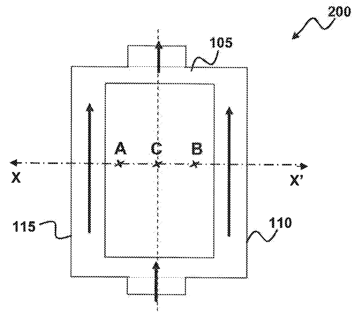
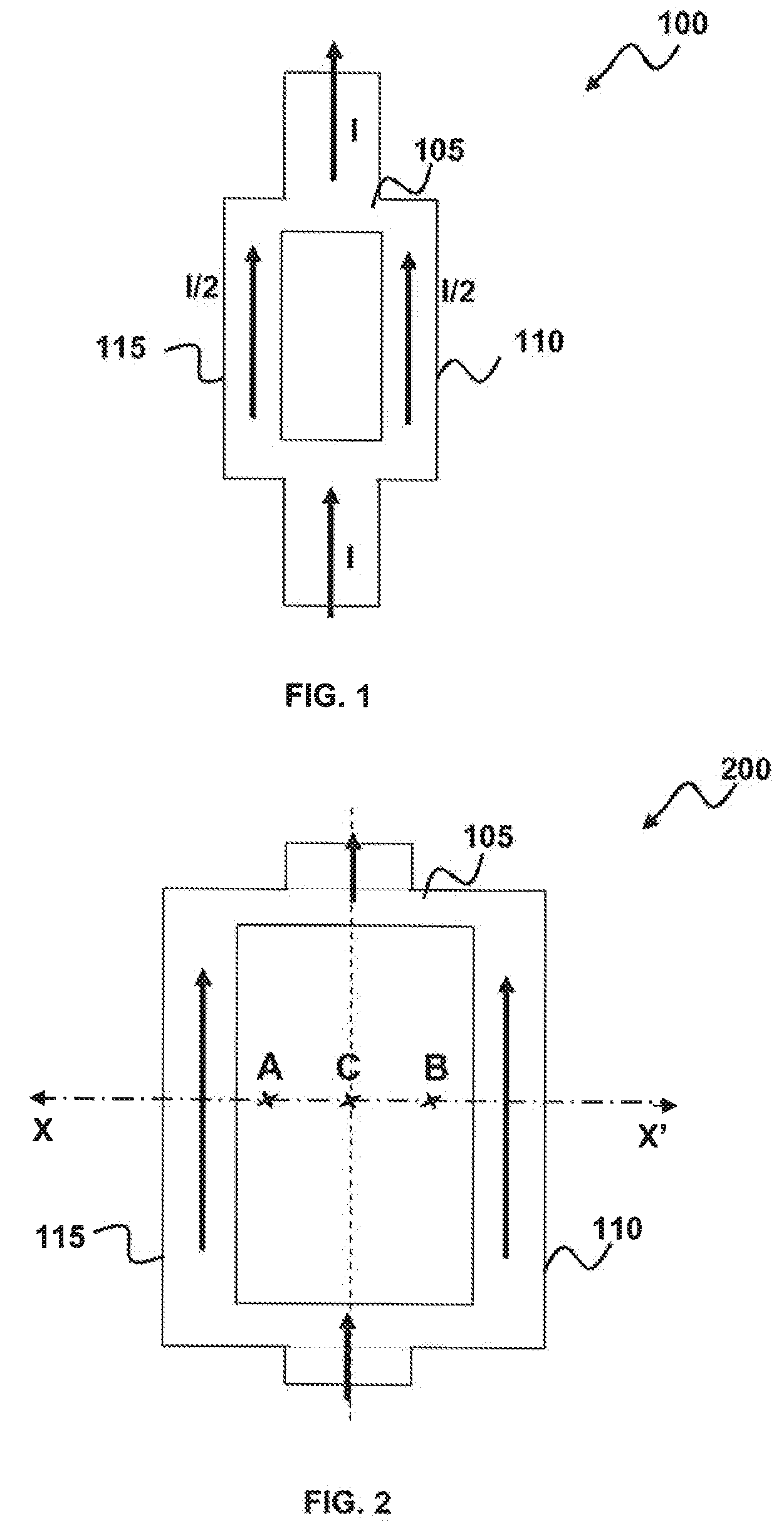
[0027]FIG. 1 illustrates an explanatory diagram of a core-less current sensor 100, which can be implemented in accordance with a preferred embodiment. The current I can be passed through a pair of parallel conductors 105. The current I divide equally between the conductors 110 and 115 and each conductor carries an equal current I / 2. The size of conductors 110 and 115 can be determined based on the permissible current density for conducting material like copper, aluminum, etc. For example, a copper conductor with a cross sectional area of 4 mm2 should be fine for currents up to 25 A.

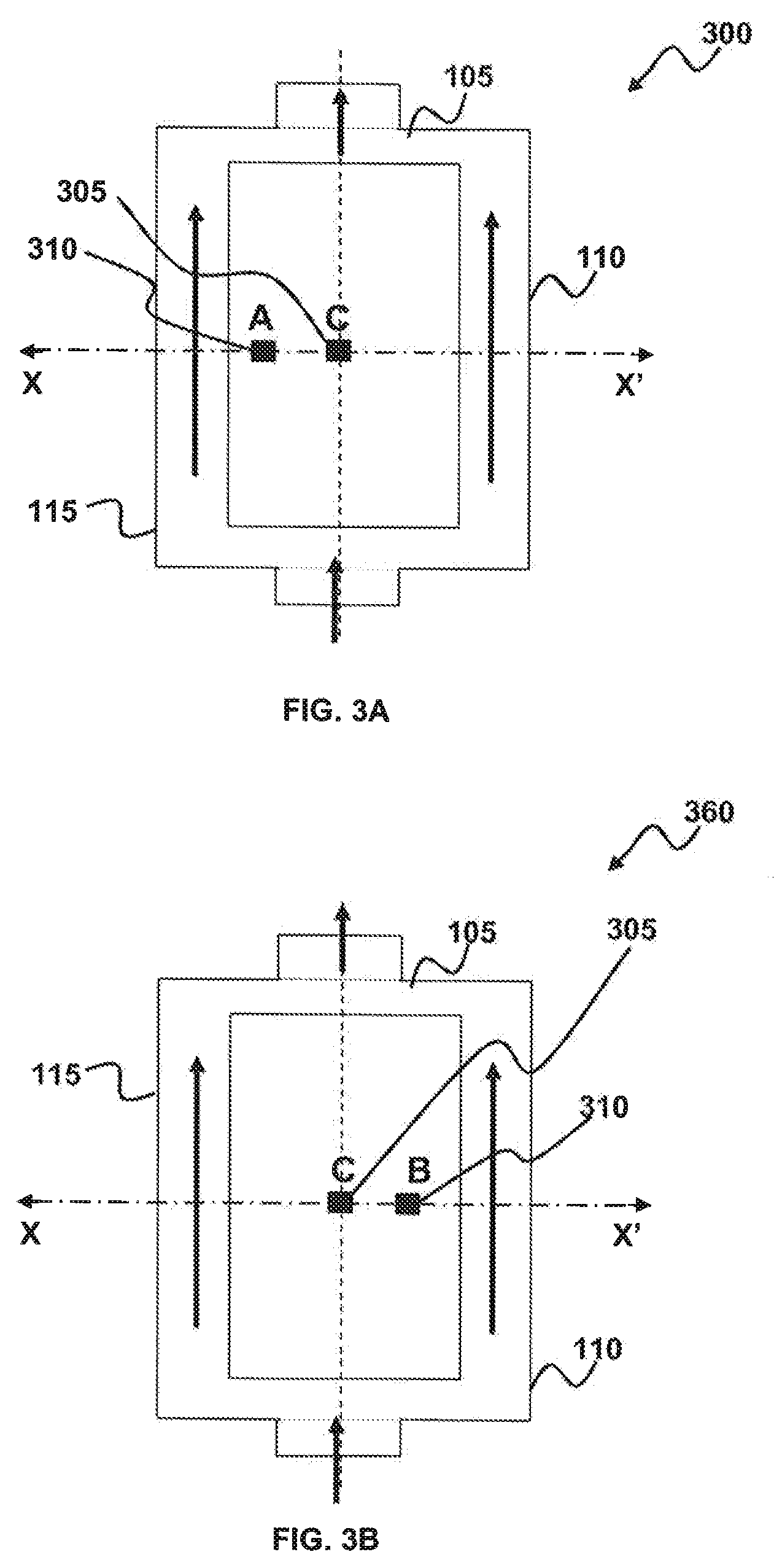
[0028]The conductors 110 and 115 can be traced out on a PCB (Printed Circuit Board) up to certain current ratings. Ratings can be determined based on the current density. The current density is given...


PUM

PropertyMeasurementUnit
currentaaaaaaaaaa
currentsaaaaaaaaaa
magneticaaaaaaaaaa

Abstract

Core-less current sensor comprises two parallel conductors carrying equal currents in the same direction. The magnetic field in mid location of the two parallel conductors carrying equal currents in the same direction for all current magnitudes is zero in absence of an external magnetic interference. Sum of magnetic fields in two points equidistant from the mid location on both the sides is zero as magnetic fields at these points are equal in magnitude and opposite in polarity for all current magnitudes and for equal amount of currents flowing through both conductors in same direction in absence of an external magnetic interference. Two sensing elements can be arranged between the two parallel conductors for sensing the magnetic field due to currents flowing through them for the purpose of current measurement. Sensor output is the difference between two outputs measured by the sensing elements. Outputs of sensing elements can vary due to external interference. As variation in the outputs of sensing elements due to external interference gets cancelled in sensor output, automatic external field compensation can be achieved.

Description

TECHNICAL FIELD[0001]Embodiments are generally related to current sensors based on magnetic field sensing techniques such as for e.g. Hall Effect, Magneto-resistive (Anisotropic Magneto-resistive, Giant Magneto-resistive, etc.) sensing etc. Embodiments are also related to the field of core-less current sensors. Embodiments are additionally related to core-less current sensors with automatic external magnetic interference protection.BACKGROUND OF THE INVENTION[0002]A variety of current measurement techniques are known, including resistive shunt, current transformer, Hall Effect based sensors and Magneto-resistive (MR) sensors. The shunt measurement technique works on the principle of Ohm's Law, while current transformer and Hall Effect based sensors utilize Ampere's Law. Each technology has its own tradeoffs. Shunts offer low cost, DC (Direct Current) and AC (Alternating Current) current sensing but insert a voltage drop and do not provide isolation. Current transformers are of low c...

Claims


Application Information

Patent Timeline
Patent Type & Authority Applications(United States)
IPC IPC(8): G01N27/72
CPCG01R33/07G01R15/207
Inventor KUMAR, SACHINTHOTADAKUMBRI, RAVIPRAKASHREDDY, GANGI RAJULA
Owner HONEYWELL INT INC
Why Eureka
Try Eureka