Air passage opening and closing device

a technology of air passage and opening and closing device, which is applied in the direction of vehicle maintenance, vehicle cleaning, manufacturing tools, etc., can solve the problems of deformation of the connection portion between the door body and the driven side gear, failure of the related art, etc., to prevent the decrease in the area of the opening portion, improve the sealing performance, and improve the sealing performance

Inactive Publication Date: 2009-01-22
DENSO CORP
View PDF10 Cites 14 Cited by
  • Summary
  • Abstract
  • Description
  • Claims
  • Application Information

AI Technical Summary

Benefits of technology

[0010]In the examination example, a hollow recessed space 32a (hollow space) is provided in the driven side gear 32. Thus, the driven side gear 32 is thinned, so that the driven side gear 32 has approximately the same thickness as that of a door body 30. In this case, the door body 30 and the driven side gear 32 have a uniform cooling rate in molding, thereby preventing a deformation of the connection portion between the door body 30 and the driven side gear 32 due to the constriction force. Provision of the recessed space 32a makes the driven gear 32 thinner so as to prevent the occurrence of the “sink”.
[0028]According to another aspect of the present invention, a method for manufacturing the air passage opening and closing device includes a step of integrally molding the door body and the driven side gear by a forming die. Furthermore, the forming die includes a cavity die and a core die that are divided into a side of the first plate surface and a side of the second plate surface, and a slide core die for forming the hollow space. In this case, a die matching position between the slide core and one of the cavity die and the core die on the side of the first plate surface is set in a portion of the door body other than a contact portion of the door body contacting the case-side seal surface, and a die matching position between the slide core and the other one of the cavity die and the core die on the side of the second plate surface is set in a portion of the driven side gear other than a contact portion of the driven side gear contacting the guide wall surface. Thus, the method has an improved sealing performance while the air passage opening and closing device prevents a decrease in area of the opening portion of the air passage.

Problems solved by technology

Detailed studies by the inventors of the present application have shown that integral molding of the door body and the driven side gear using resin may result in failure in the related art.
Thus, the molded structure of the resin due to the cooling may not be constant between the door body and the driven side gear, thereby causing deformation of a connection portion between the door body and the driven side gear due to a constriction force.

Method used


Image

  • Air passage opening and closing device
  • Air passage opening and closing device
  • Air passage opening and closing device

Examples


first embodiment

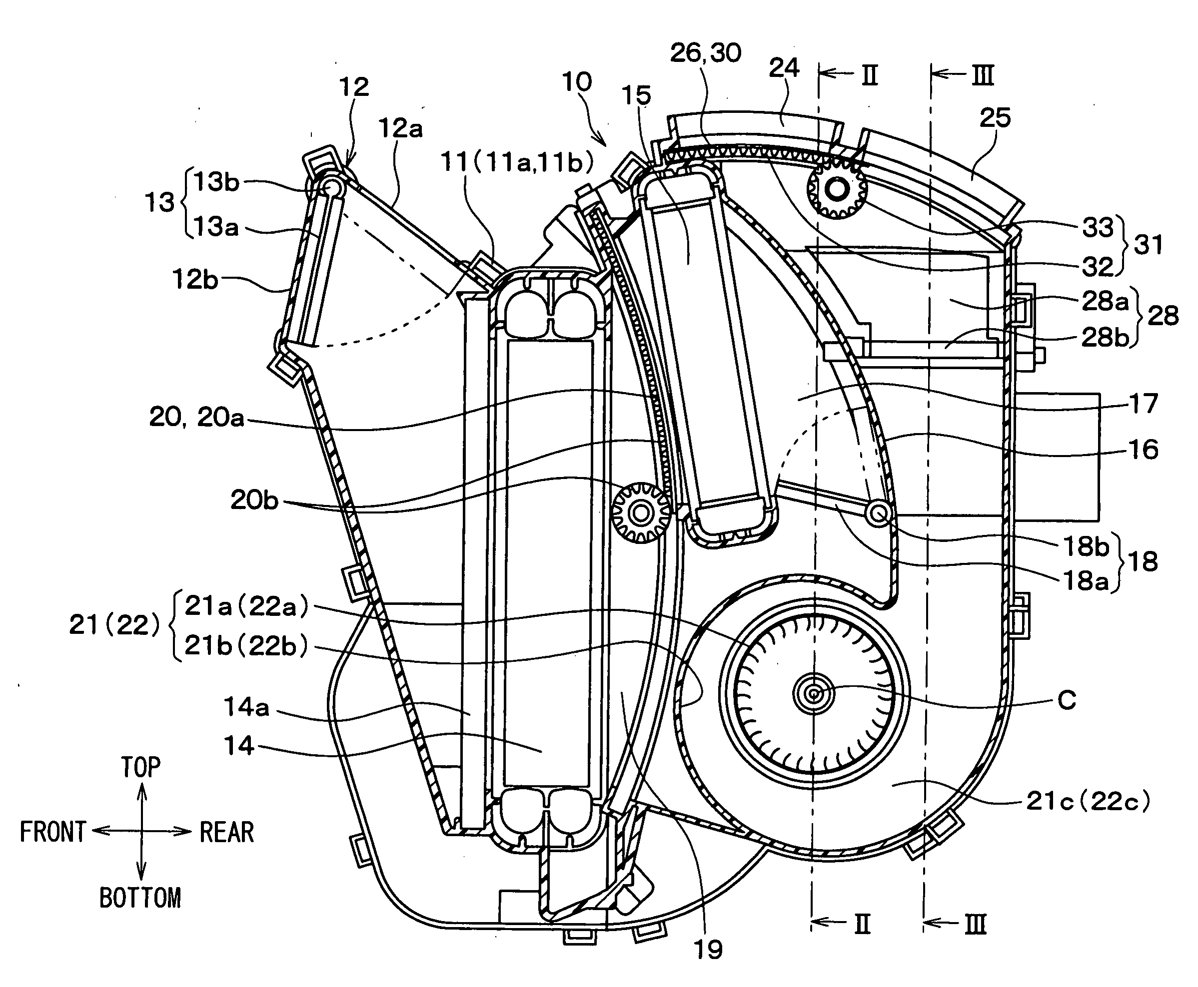
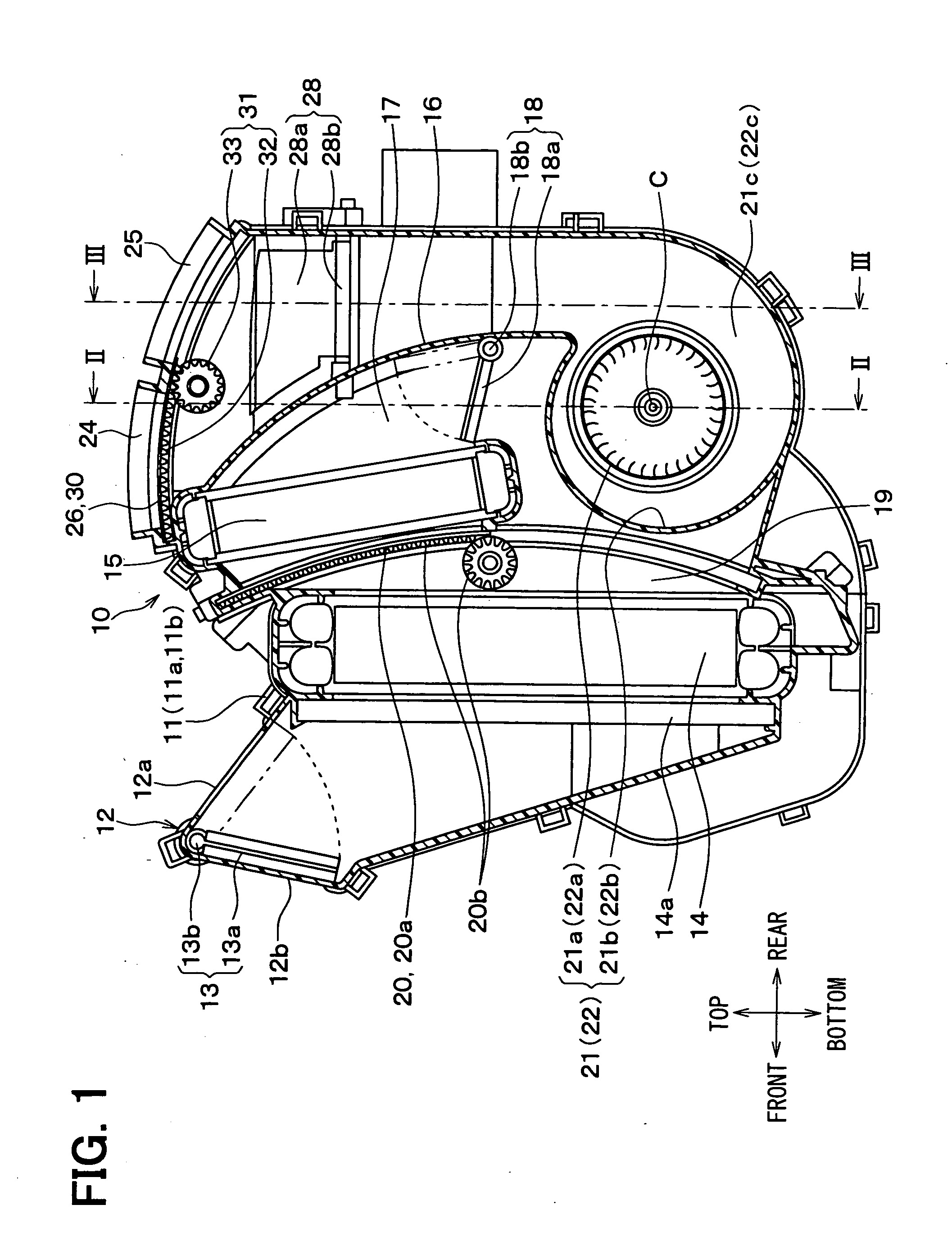
[0044]A first embodiment of the invention will be described below based on FIGS. 1 to 10B.

[0045]An interior air conditioning unit 10 is disposed substantially at a center area of a vehicle in a width direction (vehicle left-right direction) inside a dashboard (instrument panel) that is disposed at the front of a vehicle compartment. The interior air conditioning unit 10 includes a case 11 for forming an outer shell and an air passage through which air is blown toward the inside of the compartment. The case 11 has elasticity to some degree, and is molded using resin having excellent strength (for example, polypropylen).

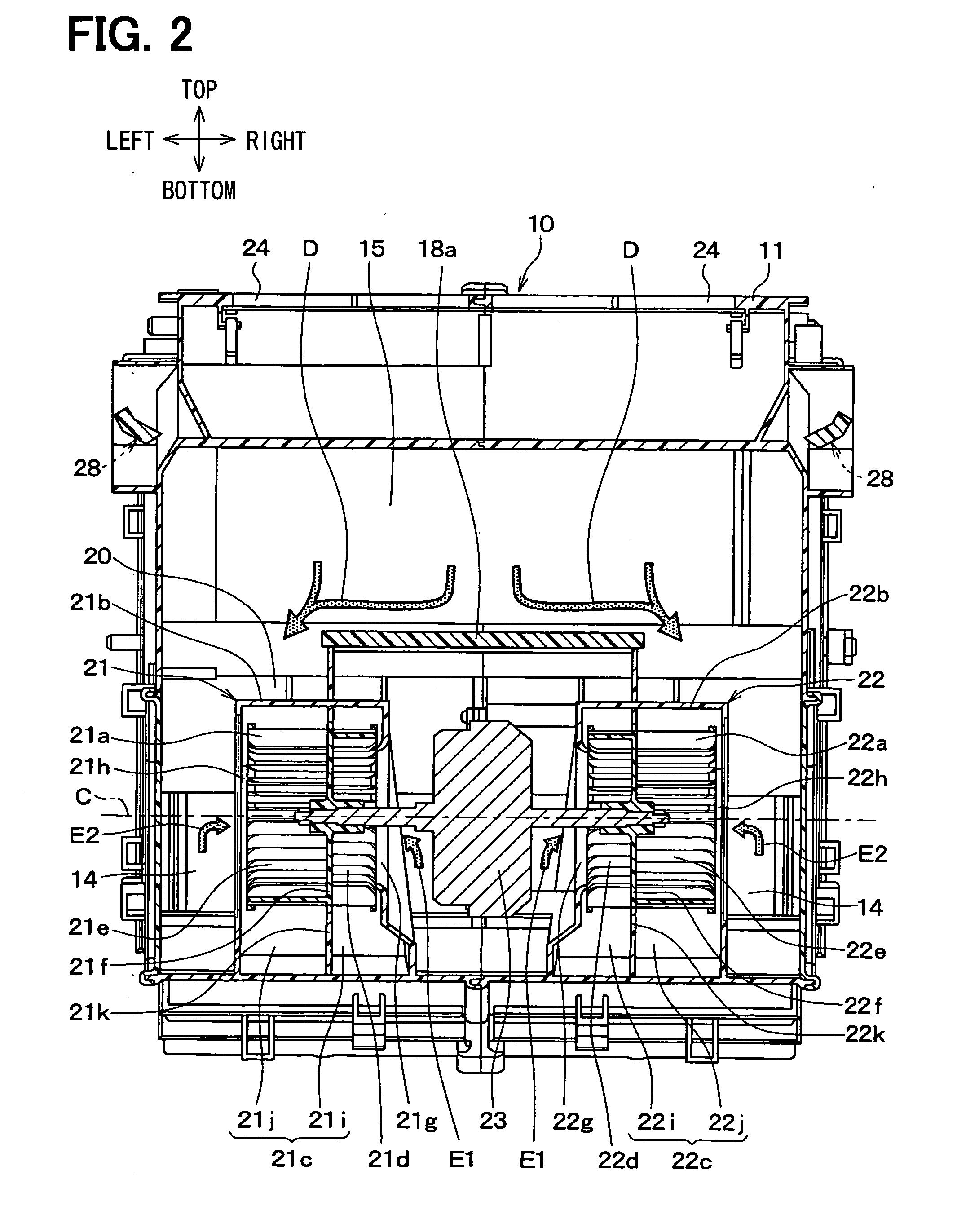
[0046]The case 11 has a division surface S (see FIG. 4 to be described later) formed vertically substantially at the center in the width direction, and can be divided into two left and right division portions 11a and 11b at the division surface S. The two left and right division portions 11a and 11b are integrally connected to each other by connection mean, such as a m...

second embodiment

[0134]In the above-described first embodiment, the recessed space 32a is laid-drawn in the door width direction W from the outside of the driven side gear 32. That is, in the above-described first embodiment, the recessed space 32a is open from the outside of the driven side gear 32 and extends toward the center side in the door width direction W. However, in a second embodiment, as shown in FIG. 11, the recessed space 32a is laid-drawn in the door width direction W from the inside of the driven side gear 32. That is, in the second embodiment, the recessed space 32a is open from the inside of the driven side gear 32 and extends toward the outside end in the door width direction W.

[0135]Thus, the second embodiment can obtain the same operation and effect as those in the first embodiment.

[0136]Furthermore, in this embodiment, the air blown toward the defroster opening 24 flows into the recessed space 32a as indicated by the arrows shown in FIG. 12, causing the plate surface 30a on the...


PUM

PropertyMeasurementUnit
suctionaaaaaaaaaa
shapeaaaaaaaaaa
widthaaaaaaaaaa

Abstract

An air passage opening and closing device includes a case forming an opening portion, a sliding door, and a gear mechanism. The case has a case-side seal surface at two edges of the opening portion in a width direction of a door body of the sliding door, on which a first plate surface of the door body abuts. The gear mechanism includes a driven side gear molded integrally with the door body using resin. The driven side gear protrudes from a second plate surface of the door body on a side opposite to the first plate surface, and extends in parallel with a movement direction of the sliding door, at two edge portions of the second plate surface in the width direction. In addition, the driven side gear has a hollow space opened toward a direction parallel to the width direction.

Description

CROSS REFERENCE TO RELATED APPLICATION[0001]This application is based on Japanese Patent Applications No. 2007-186918 filed on Jul. 18, 2007, and No. 2008-053049 filed on Mar. 4, 2008, the contents of which are incorporated herein by reference in its entirety.FIELD OF THE INVENTION[0002]The present invention relates to an air passage opening and closing device for opening and closing an opening portion of an air passage by using a sliding door, and to a method of manufacturing the device. The air passage opening and closing device is suitable for use in an air conditioner for a vehicle, for example.BACKGROUND OF THE INVENTION[0003]Conventionally, an air conditioner for a vehicle using such an air passage opening and closing device is disclosed in, for example, U.S. Pat. No. 6,450,877 (corresponding to JP Patent No. 3824105). In the air conditioner of the related art, a sliding door including a plate-like door body is slidably disposed in a case for forming an opening portion of an a...

Claims


Application Information

Patent Timeline
Patent Type & Authority Applications(United States)
IPC IPC(8): B60H1/00
CPCB60H1/00692Y10T29/49908B60H2001/00714
Inventor SUZUKI, YOSHIHIROTOKUNAGA, TAKAHIROSAKAKI, YOSHIKAZU
Owner DENSO CORP
Why Eureka
Try Eureka