Adaptive Tuning To Improve Demodulator Performance

a demodulator and adaptive tuning technology, applied in the direction of automatic frequency control details, resonant circuit details, electrical characteristics varying frequency control, etc., can solve the problems of reducing the communication speed and data communication speed of the user, reducing the accuracy of data receiving, and reducing the error rate of receiving data. , to achieve the effect of preventing frequency drift, reducing error rate and reducing error ra

Active Publication Date: 2009-01-22
ARRIS ENTERPRISES LLC
View PDF8 Cites 5 Cited by
  • Summary
  • Abstract
  • Description
  • Claims
  • Application Information

AI Technical Summary

Benefits of technology

[0012]The present invention enables more accurate tuning to an intended transmission frequency which reduces errors in receiving data. In a preferred implementation the invention may be an automated process which reduces a frequency offset from the intended frequency and to prevent frequency drifting in the receiver. Use of the present invention may allow a network operator to more reliably deliver data rates and improve signal quality to its customers.

Problems solved by technology

When a modem locks onto a frequency which is not the actual transmission frequency data will likely be received by the modem but the communications will not be optimal.
In some instances, the error rates in the data received, e.g. the packet error rate and / or the bit error rate, may be sufficient to sustain the channel lock but may greatly reduce the communication speed and the quality of the data received.
As a result, a user may not receive the data communications speeds from an operator at levels advertised by an operator.
A user may also experience frequent loss of data packets which may impair communications with a network element, and may be particularly noticeable in voice communications, e.g. VoIP calls, video applications, and file downloads.

Method used


Image

  • Adaptive Tuning To Improve Demodulator Performance
  • Adaptive Tuning To Improve Demodulator Performance
  • Adaptive Tuning To Improve Demodulator Performance

Examples


Embodiment Construction

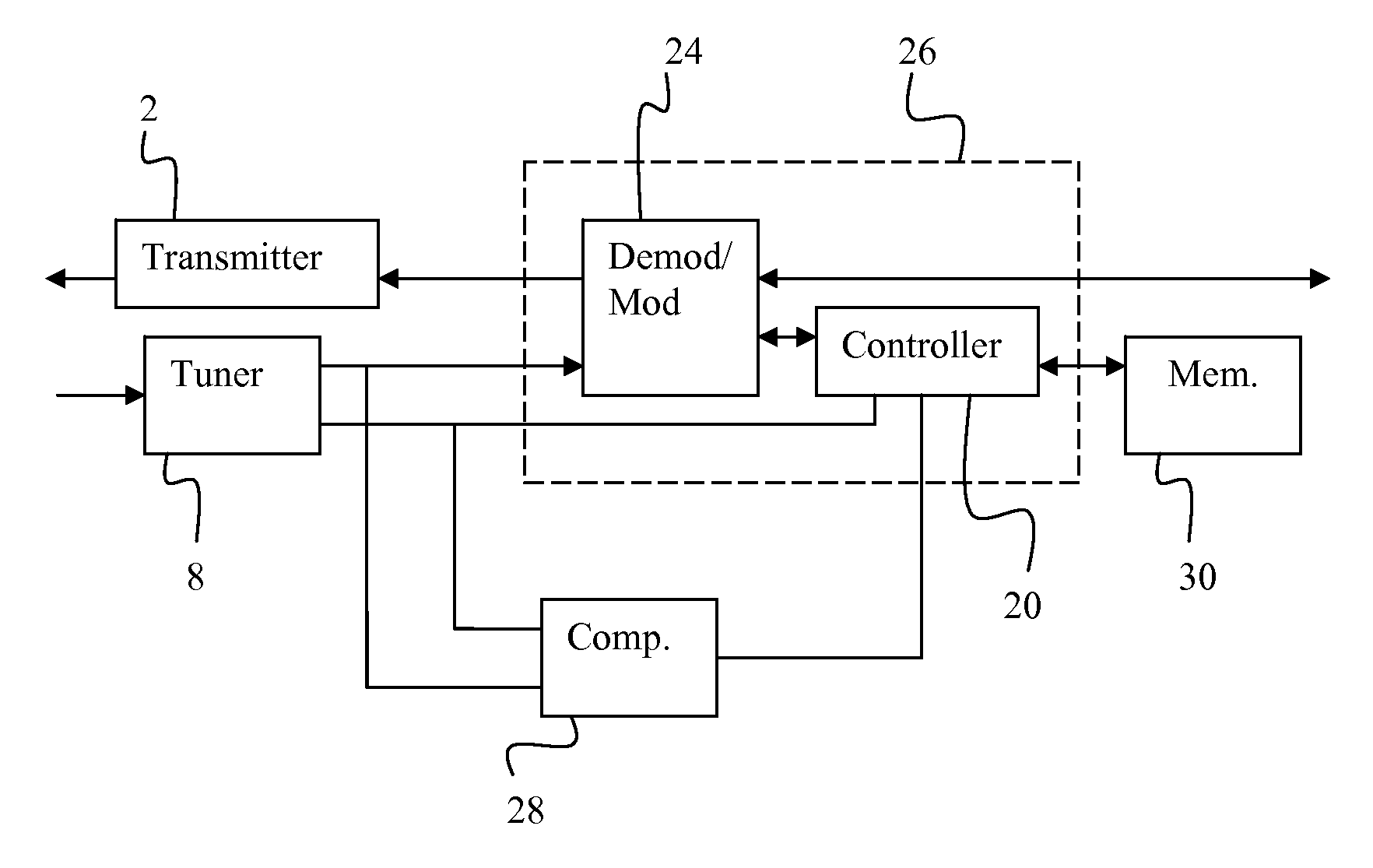
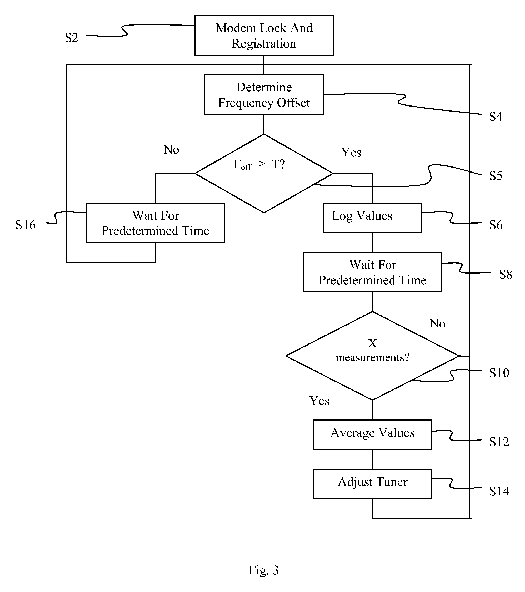
[0017]The present invention improves performance of a network element, such as a modem, set top box (STB), or media terminal adapter (MTA) unit, by ensuring that the receiver in the network element receives communications on the transmitted frequency of a network operator. The present invention determines the frequency offset between the frequency on which the receiver has locked and the intended frequency being transmitted by the operator. The difference in the frequency offset is reduced to be below a predetermined value. The frequency offset is continuously monitored to correct for offset due to drift in circuit components such as a crystal oscillator in the receiver.

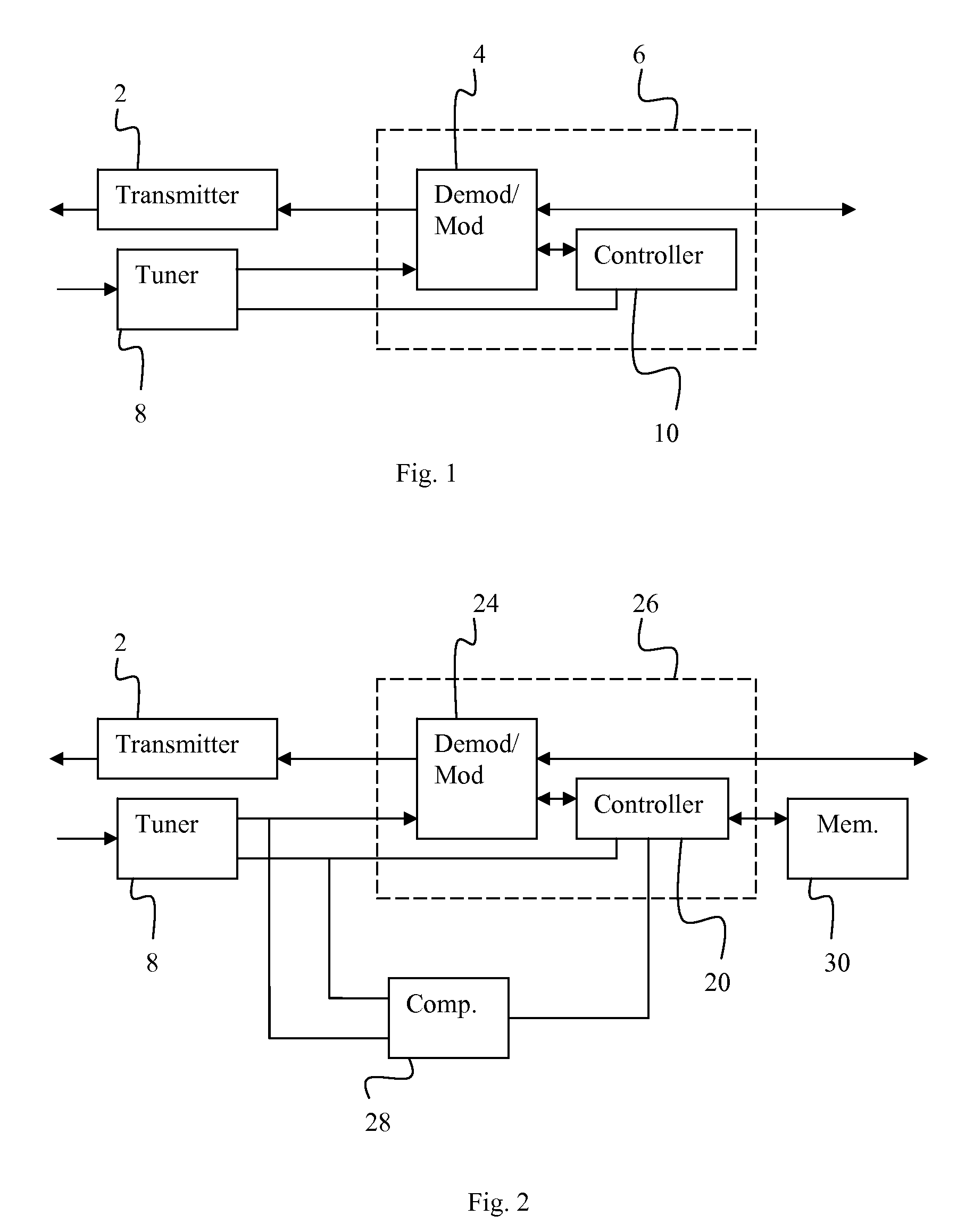
[0018]Several basic components of a conventional receiver are illustrated in FIG. 1. As illustrated in FIG. 1, a tuner 8 receives a downstream signal from a network, such as from a headend of a CATV network. In the installation of the network element on the network, or turning on the power of the network element, the...


PUM


Abstract

A receiver is tuned to a transmission frequency of a data signal after the receiver has already locked onto a frequency carrying the data signal. A frequency offset between a locked frequency of a tuner on the receiver and the actual transmission frequency is determined by a comparator. If the frequency offset is greater than a threshold value, then the tuner is stepped to another frequency and the frequency offset is determined again. The direction of the tuning step can be determined by comparing multiple frequency offsets. An average value of multiple frequency offset measurements may also be used to determine if the tuner should retune to another frequency by comparison with the threshold value.

Description

[0001]This application claims priority to U.S. provisional application Ser. No. 60 / 951,116 entitled, “Adaptive Tuning To Improve Demodulator Performance”, filed on Jul. 20, 2007, the content of which is incorporated herein by reference in its entirety.FIELD OF THE INVENTION[0002]The present invention relates to a method and apparatus for adaptive tuning. More particularly, the present invention relates to a method and apparatus for adaptive tuning to improve demodulator performance.BACKGROUND OF THE INVENTION[0003]A typical broadband communication system, such as a coaxial cable communication system (CATV), provides downstream data communications from a centralized node or headend to modems of many users. The downstream data communications are provided from the nodes or headends at specific frequencies. The communication system operators, e.g. multi-service operators (MSOs) may use several data communication frequencies and different frequencies are often used by different operators...

Claims


Application Information

Patent Timeline
Patent Type & Authority Applications(United States)
IPC IPC(8): H04B1/06
CPCH03J1/0091H03J2200/02H03J7/04
Inventor PATEL, DIPAK R.KANKIPATI, NAVANEETHA KRISHNAMARTIN, CRAIG G.
Owner ARRIS ENTERPRISES LLC
Why Eureka
Try Eureka