Method for determining the centre of gravity for an automotive vehicle

a technology for automotive vehicles and centre of gravity, applied in the direction of hardware monitoring, structural/machine measurement, registration/indicating, etc., can solve the problems that the height of the cg cannot be easily inferred, cannot be measured online, and substantially in real time during the operation of the vehicle,

Inactive Publication Date: 2009-01-22
NAT UNIV OF IRELAND MAYNOOTH
View PDF12 Cites 15 Cited by
  • Summary
  • Abstract
  • Description
  • Claims
  • Application Information

AI Technical Summary

Benefits of technology

[0029]Each of these aspects of the present invention can be implemented in conventional vehicle ECU (electronic control units) to detect, for example, over/under inflation of an indi

Problems solved by technology

However, the CG height can neither be measured online (that is to say, substantially in real time during operation of a vehicle) using known systems, nor it can be inferred easily, and is subject to variations that depend on vehicle loadings, and other factors.
It is the view of the present applicants that a rollover mitigation controller that is designed using a single set of model parameters may

Method used


Image

  • Method for determining the centre of gravity for an automotive vehicle
  • Method for determining the centre of gravity for an automotive vehicle
  • Method for determining the centre of gravity for an automotive vehicle

Examples


first embodiment

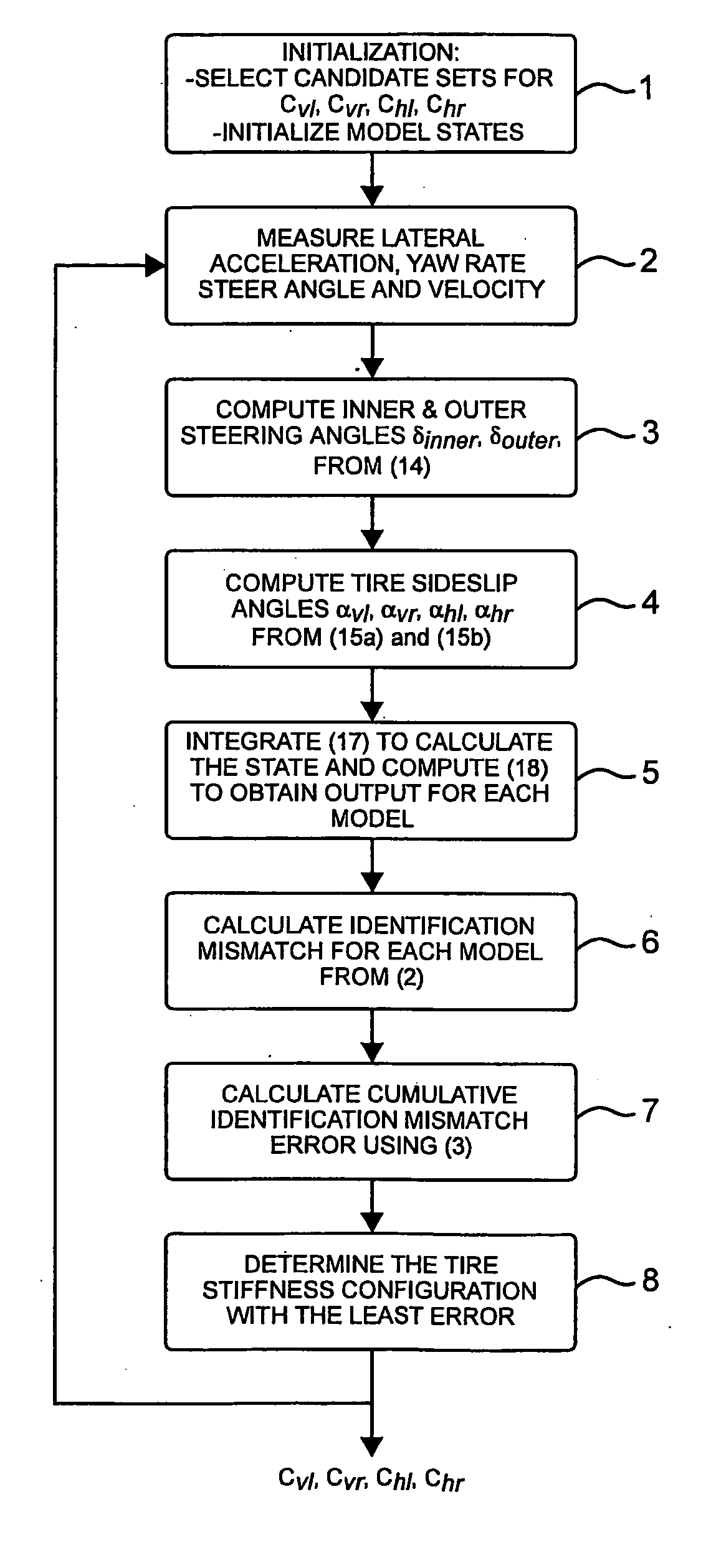
[0103]In Step 6 of FIG. 8, the identification error ei(t) corresponding to the i-th model is calculated using equation (2) from the first embodiment, where the multiple model estimation structure to compute ei(t) is depicted in FIG. 14.

[0104]In Step 7 of FIG. 8, the cumulative identification error Ji(t) corresponding to the i-th model identification error is calculated using Equation (3) from the first embodiment, where ζ, γ, and λ are non-negative design parameters which can be appropriately chosen to weigh instantaneous and steady-state identification errors.

[0105]In Step 8 of FIG. 8, the model with the least cumulative identification error is calculated using equation (4) of the first embodiment and the corresponding parameter values (Cvl—p, Cvr—q, Chl—r, Chr—s) are obtained.

[0106]In the most basic implementation of the method depicted in FIG. 8, the models are constructed to detect a fixed and predetermined level of stiffness reduction in any combinations of the tires. In this c...

fourth embodiment

[0108]An aim of the fourth embodiment is to provide an arrangement for dynamically determining the individual tire cornering stiffness values Cvl, Cvr, Chl, Chr for each of the four tires, taking into account time variations in the vertical loads FZvl, FZvr, FZhl, FZhr on each tire.

[0109]To begin, the side force acting on each tire Sij, where the first index i={v,h} denotes “front” and “rear”, and second index j={l,r} denotes “left” and “right”, is given by:

Sij=Cij(FZij)αij, where i={v,h} and j={l,r}  (19)

where αij is the side slip angle of the corresponding tires and tire stiffnesses Cij(FZij) are time-varying functions of the corresponding vertical forces.

third embodiment

[0110]As in the third embodiment, tire cornering stiffness parameters Cij(FZij) are assumed to be unknown but their nominal values corresponding to manufacturer-recommended pressure levels and for varying vertical loads are known. Again, this embodiment relies on the assumption that when and if any of the time-varying tire cornering stiffness values (and effectively the corresponding lateral forces) are found to be smaller than nominal levels by a certain threshold amount, then the corresponding tires must either have a non-optimal pressure (i.e., under / over inflation) and / or a persistent loss of grip as a result of reduced thread depth. Note that the variation of the tire cornering stiffness with respect to loss of inflation pressure or loss of tire thread depth will vary between different tire types, but these can be measured off-line by tire manufacturers through test rig evaluations.

[0111]Referring now to FIG. 9 which shows a functional block diagram describing an indirect estim...


PUM


Abstract

Methods for determining the height, horizontal position, and lateral position of the centre of gravity of a vehicle are disclosed. The methods comprise constructing a plurality of models of vehicle behaviour, each model including a plurality of parameters that determine vehicle behaviour including parameters that define the position of the centre of gravity. The method then measures actual vehicle behaviour during operation of the vehicle. The actual behaviour and the behaviour predicted by the models are then compared to determine which of the models most effectively predicts behaviour of the vehicle. The model that is most effective in predicting the actual behaviour of the vehicle is then assumed to include amongst its parameters an estimate of the position of the centre of gravity of the vehicle.

Description

[0001]This application is a Continuation-in-Part of International application PCT / EP2007 / 001584 filed Feb. 23, 2007, which claims the benefit of Irish patent application S2006 / 0162 filed Mar. 3, 2006, the disclosures of which are incorporated herein by reference in their entireties.FIELD OF THE INVENTION[0002]This invention relates to a method for determining the centre of gravity for an automotive vehicle. More specifically, embodiments of the invention provide a method for determining height, horizontal location and lateral position of the centre of gravity. It has particular, but not exclusive, application for use with passive and active rollover detection and prevention systems.BACKGROUND OF THE INVENTION[0003]According to the United States National Highway Traffic Safety Administration, rollover accidents in the U.S., during 2002, were responsible for nearly 33% of the total passenger fatalities whereas they accounted for only 3% of the total passenger vehicle accidents. If a r...

Claims


Application Information

Patent Timeline
IPC IPC(8): G06F17/00
CPCG01M1/122
Inventor SHORTEN, ROBERTSOLMAZ, SELIMAKAR, MEHMET
Owner NAT UNIV OF IRELAND MAYNOOTH
Why Eureka
Try Eureka