AINS enhanced survey instrument

a survey instrument and enhanced technology, applied in the field of survey instruments, can solve the problem of prohibitively expensive solutions for strictly three-axis tilt sensors

Inactive Publication Date: 2009-01-22
APPLANIX
View PDF16 Cites 111 Cited by
  • Summary
  • Abstract
  • Description
  • Claims
  • Application Information

AI Technical Summary

Problems solved by technology

At the time of this disclosure, the cost of an AINS that has a sufficient orientation or Euler angle accuracy to achieve sub-centimeter relative position error over one meter is sufficiently high to make the AINS strictly as a three-axis tilt sensor a prohibitively expensive solution.

Method used


Image

  • AINS enhanced survey instrument
  • AINS enhanced survey instrument
  • AINS enhanced survey instrument

Examples


Embodiment Construction

[0035]Aided Inertial Navigation System (AINS)

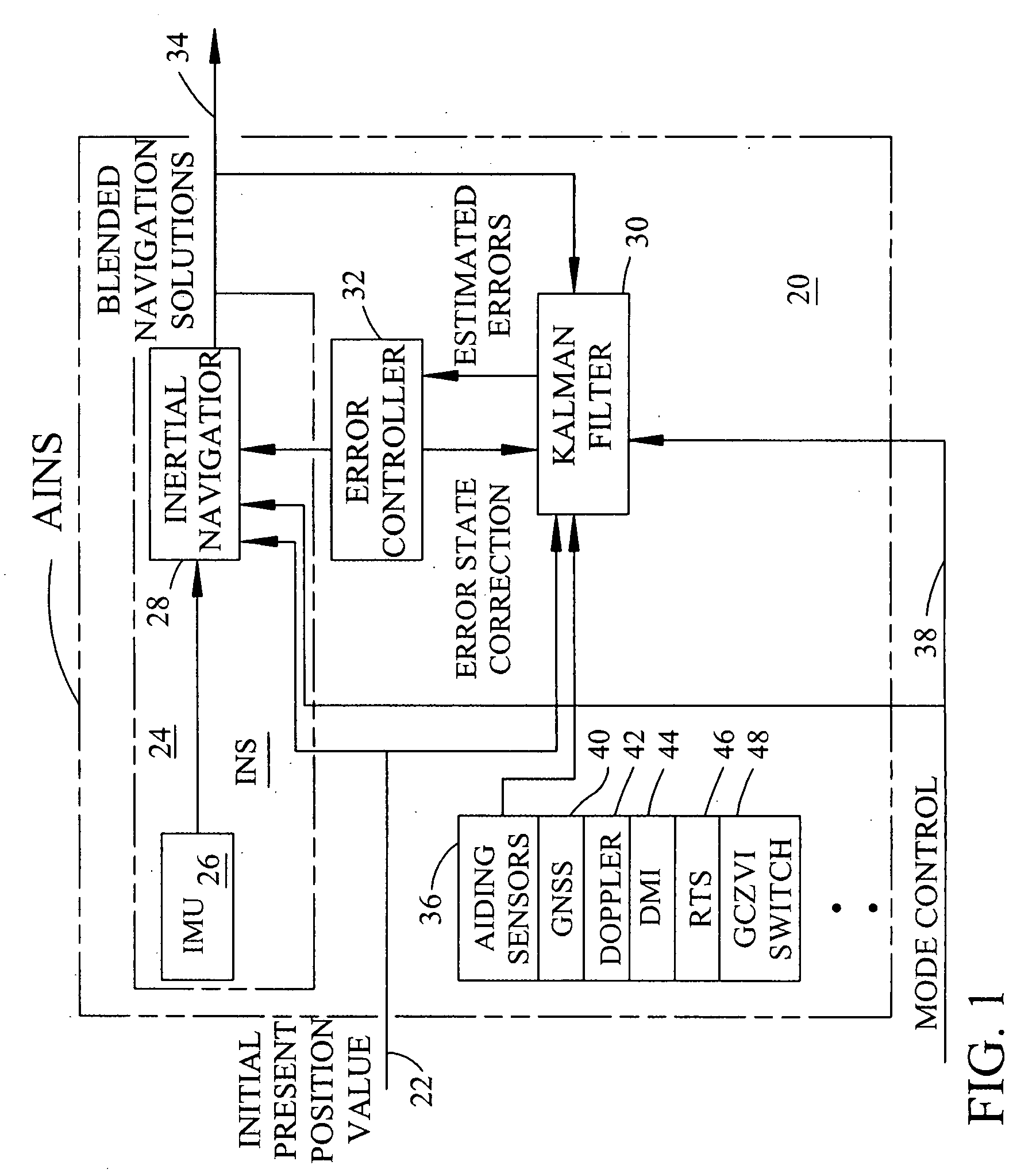
[0036]FIG. 1 is a block diagram that shows the architecture of a generic aided inertial navigation system (AINS) represented by phantom block 20. The AINS 20 is provided with an initial present position input from a keyboard or other input device (not shown) on a signal line indicated as the INITIAL PRESENT POSITION VALUE signal path 22. Phantom block 24 represents and contains the elements of an inertial navigation system (INS). The INS 24 block represent an inertial measurement unit (IMU) 26 and block 28 to represent an INERTIAL NAVIGATOR 28. The INERTIAL NAVIGATOR 28 performs alignment and inertial navigation computational functions using data from the IMU 26. FIG. 1 shows the IMU 26 and the INERTIAL NAVIGATOR 28 coupled together to perform the function of the INS 24.

[0037]Block 30 represents a KALMAN FILTER. Block 32 represents an ERROR CONTROLLER function that estimates INS 24 errors using inputs from the KALMAN FILTER 30 and provide...


PUM


Abstract

The invention comprises a survey pole having a survey pole bottom end, with a position-transducer coupled to a survey pole top end. A ground contact spike is on the bottom end. The survey pole uses an AINS as a combined tilt and heading sensor. The AINS provides heading and Euler angle outputs characterizing the tilt of the survey pole. The heading and Euler angle outputs are used by a computer and program to perform position transfers from a position-transducer at the pole top end to the GCZVI switch or spike on the ground using a set of position offset or transfer equations. The position-transducer is either a GNSS or an RTS serving as a position-transducer. The transfer of the position data from the position of the position-transducer provides the earth referenced or grid referenced position of the spike at the survey pole survey bottom end.

Description

BACKGROUND OF THE INVENTION AND RELATED ART[0001]This application incorporates by reference U.S. Pat. No. 6,853,909 B2 for a “Walking Stick Navigator For Position Determination” which issued Feb. 8, 2005 and U.S. Pat. No. 6,834,234 B2 for an “AINS Land Surveyor System With Reprocessing, AINS-LSSRP” which issued on Dec. 24, 2004 in their entirety, each having a common inventor and assignee. U.S. Pat. No. 6,594,617 B2 for A Precise Pedometer Navigator issued on Jul. 15, 2003 has a common inventor and assignee and although less relevant than the preceding patents, is also incorporated by reference in its entirety. This application also incorporates by reference U.S. Pat. No. 5,512,905 for a “Survey Pole-Tilt Sensor For Surveyor Range Survey Pole”, issued on 30 Apr. 1996 to Mark E. Nichols et al. and assigned to Trimble Navigation Limited. U.S. Pat. Nos. 6,594,617 B2, 6,834,234 B2 and 6,853,909 B2 are assigned to Applanix Corporation, which is wholly owned by Trimble Navigation Limited....

Claims


Application Information

Patent Timeline
Patent Type & Authority Applications(United States)
IPC IPC(8): G01C21/00G06F19/00
CPCG01C21/12G01C15/06
Inventor SCHERZINGER, BRUNO M.
Owner APPLANIX
Why Eureka
Try Eureka