System and Method for Pseudo-Random Test Pattern Memory Allocation for Processor Design Verification and Validation

a technology of design verification and memory allocation, applied in the field of system and method for pseudo-random test pattern memory allocation for processor design verification and validation, can solve the problems of complex test scenarios during processor execution, insufficient test coverage,

Inactive Publication Date: 2009-01-22
IBM CORP
View PDF7 Cites 20 Cited by
  • Summary
  • Abstract
  • Description
  • Claims
  • Application Information

AI Technical Summary

Benefits of technology

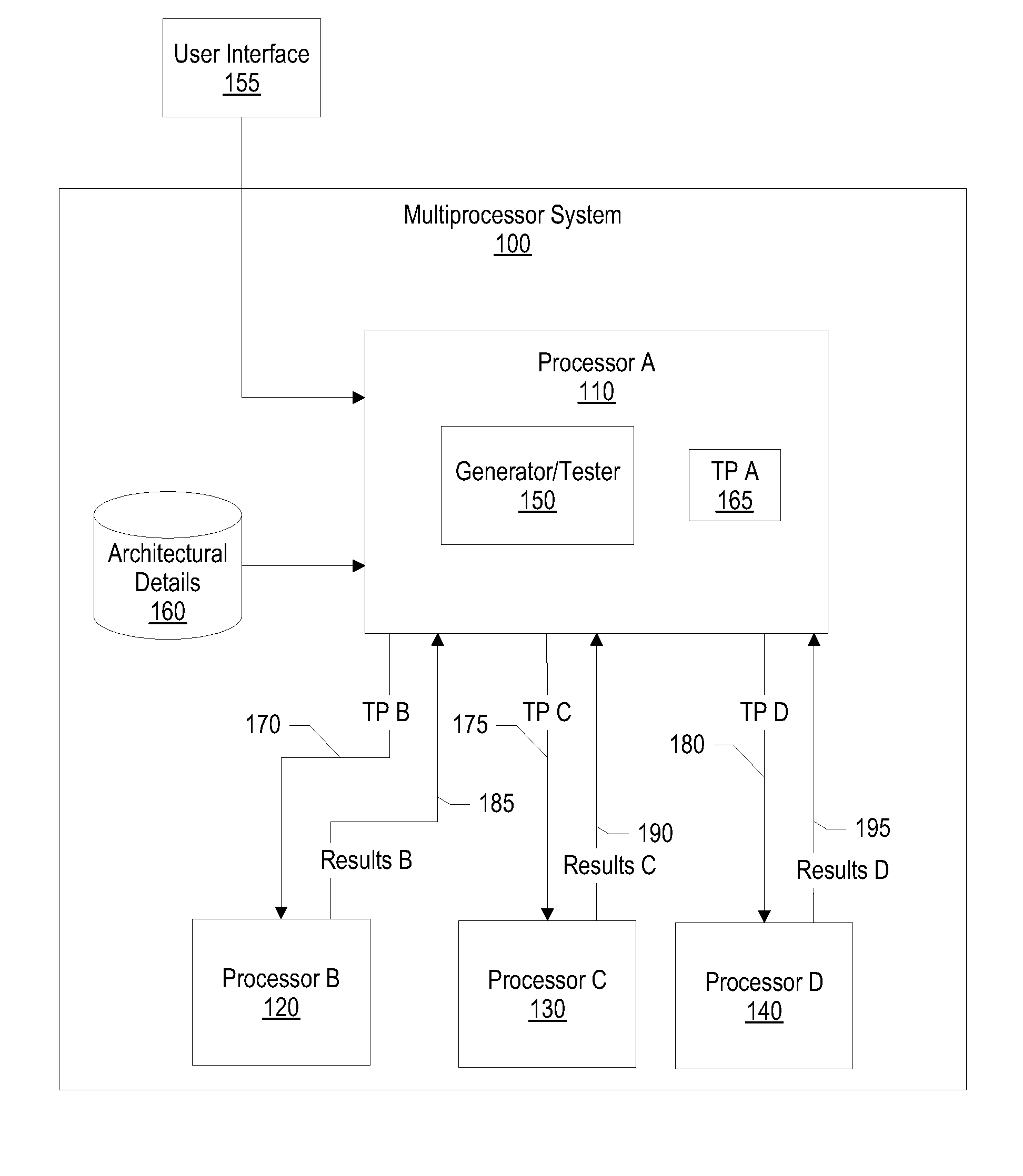
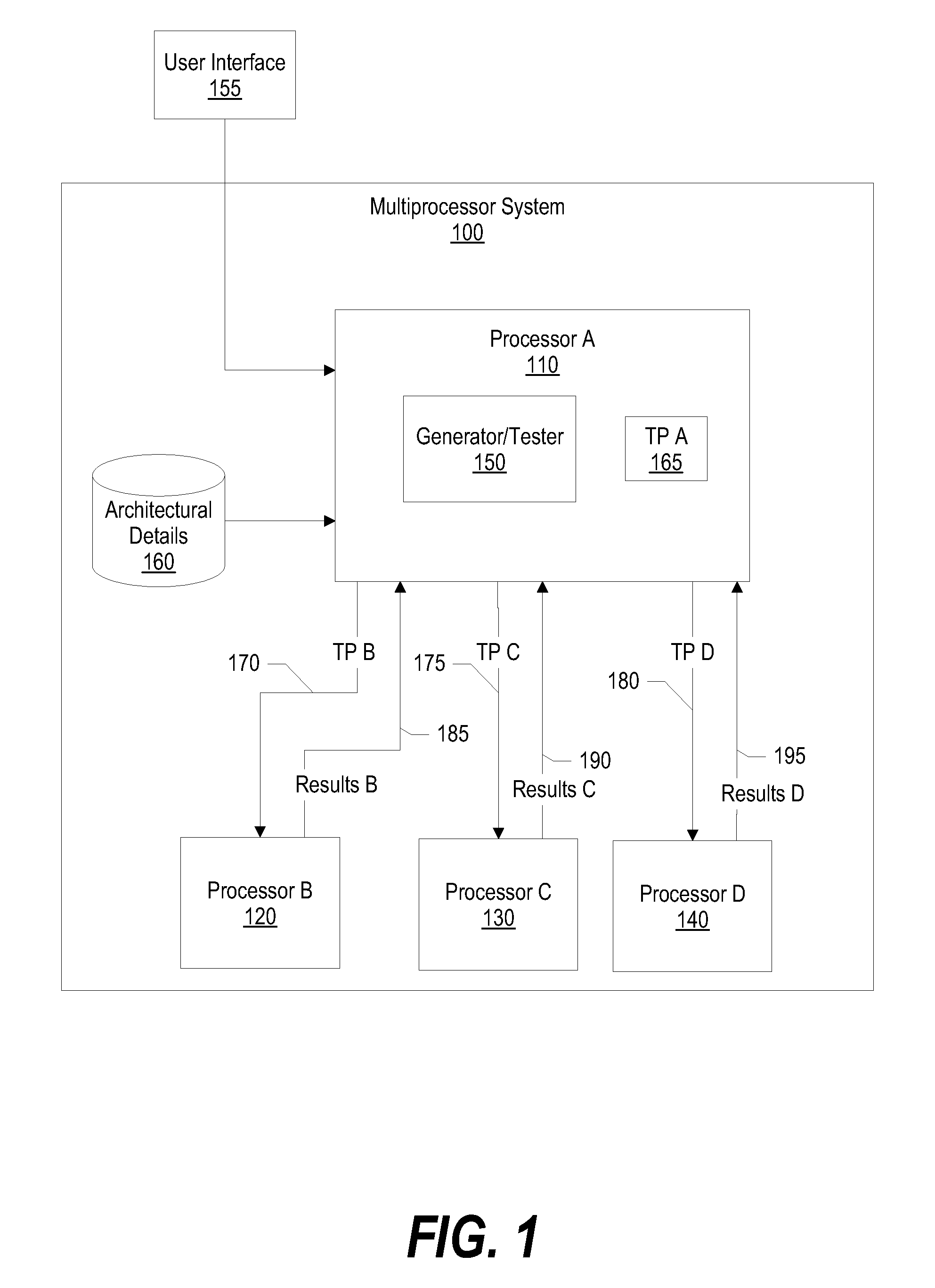
[0008]It has been discovered that the aforementioned challenges are resolved using a system and method to pseudo-randomly allocate page table memory for test pattern instructions and data, which results in complex test scenarios during processor execution. In doing so, the page table memory is distributed across processors and across multiple test patterns, such as when a processor executes “n” test patterns. In addition, the page table memory is allocated using a “true” sharing mode or a “false” sharing mode. The false sharing mode provides flexibility of performing error detection checks, such as cyclic redundancy checks (CRC), on the test pattern results. In addition, since a processor comprises sub units such as a cache, a TLB (translation look aside buffer), an SLB (segment look aside buffer), an MMU (memory management unit), and data / instruction pre-fetch engines, the test patterns effectively use the page table memory to test each of the sub units.
[0010]In one embodiment that includes multi-processors, the invention described herein produces complex test scenario results when one processor executes in virtual mode and another processor executes in real mode while both processors are attempting to access a page table memory (data, instruction or for translation).

Problems solved by technology

This decision is critical due to the fact that memory allocation affects test coverage.
As a result, the processor testing tool may allocate memory that, in turn, does not provide adequate test coverage.
It has been discovered that the aforementioned challenges are resolved using a system and method to pseudo-randomly allocate page table memory for test pattern instructions and data, which results in complex test scenarios during processor execution.

Method used


Image

  • System and Method for Pseudo-Random Test Pattern Memory Allocation for Processor Design Verification and Validation
  • System and Method for Pseudo-Random Test Pattern Memory Allocation for Processor Design Verification and Validation
  • System and Method for Pseudo-Random Test Pattern Memory Allocation for Processor Design Verification and Validation

Examples


first embodiment

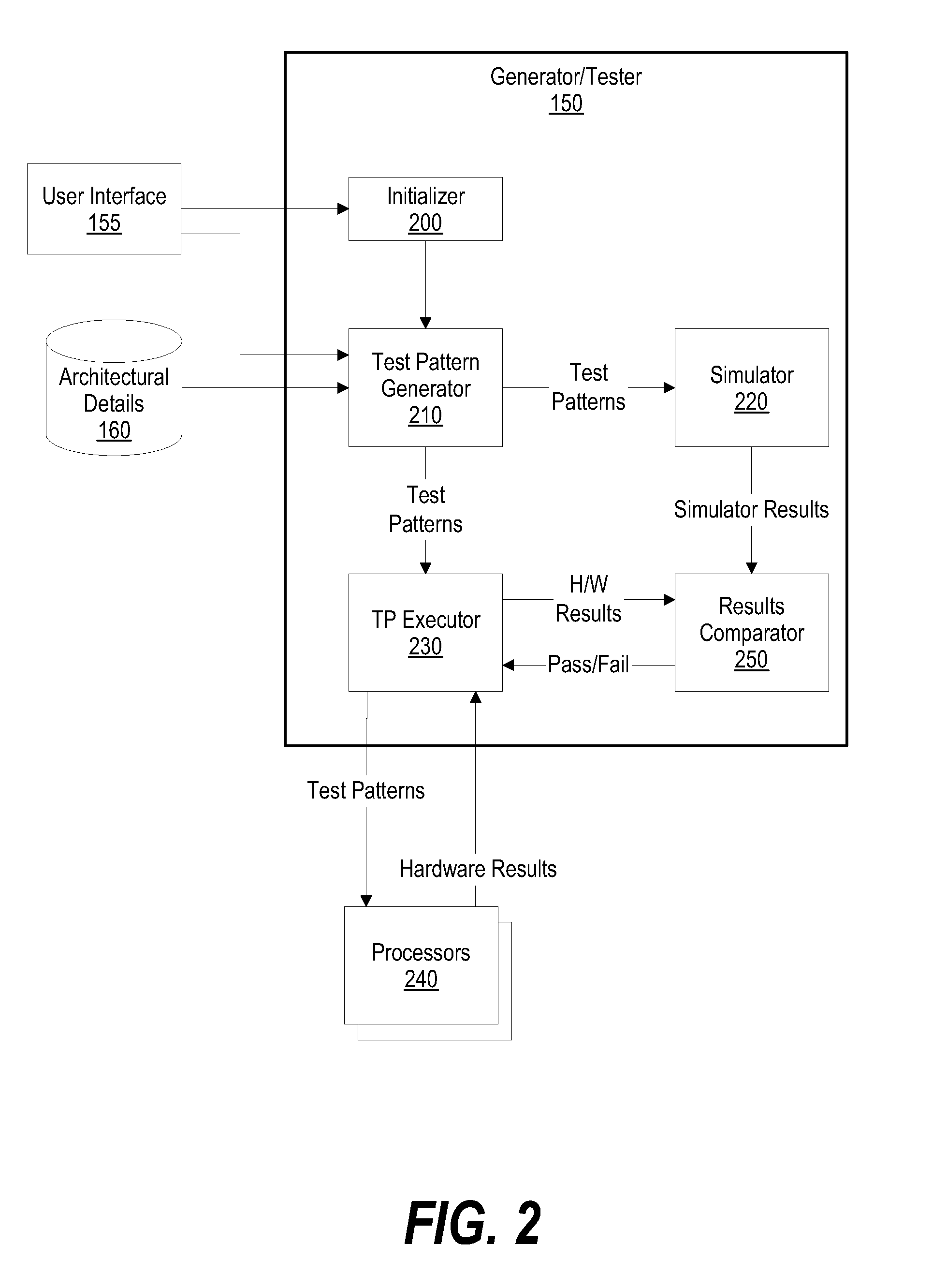
[0049]In a first embodiment, test pattern generator 500 generates one test pattern for executing a particular number of times on a processor. In this embodiment, test pattern generator 500 provides the test pattern to test pattern simulator 510 that, in turn, simulates the test pattern and returns simulation results (simulation error detection check values, such as CRC values) to test pattern generator 500. Test pattern generator 500 then provides the test pattern, along with the simulation error detection check values, to test pattern executor 520, which provides them to scheduler 530. Scheduler 530 schedules the test pattern to dispatcher 540, which dispatches the test pattern to processor 550.

[0050]Continuing with the first embodiment, processor 550 executes the test pattern and provides hardware results to results comparator 570, such as a CRC comparator. Scheduler 530 instructs results comparator 570 to compute hardware error detection check values using the hardware results, a...

second embodiment

[0051]In a second embodiment, test pattern generator 500 generates a set of “n” test patterns per processor for executing a particular number of times on a plurality of processors (see FIGS. 6, 7, and corresponding text for further details). In this embodiment, test pattern generator 500 provides the test patterns, for processor 550, to test pattern simulator 510 that, in turn, simulates the test patterns and returns simulation results (simulation error detection check values) to test pattern generator 500. In turn, test pattern generator 500 provides the test patterns, along with the simulation results, to test pattern executor 520, which provides them to scheduler 530. Scheduler 530 schedules one of the test patterns to dispatcher 540, which dispatches the test pattern to processor 550.

[0052]Continuing with the second embodiment, processor 550 executes the test pattern and provides hardware results to results comparator 570. Scheduler 530 instructs error detection check comparator...

third embodiment

[0053]In a third embodiment, test pattern generator 500 generates a test pattern that is independent of initial data values. In this embodiment, test pattern generator 500 provides the test pattern, along with an initial set of data values, to test pattern simulator 510. Test pattern simulator 500 simulates the test pattern and produces a simulation result (simulation error detection check values). Test pattern simulator 510 then uses the simulation results as input values for a second test pattern execution round. Test pattern simulator 510 continues to simulate the test pattern and use the test pattern's simulation results as input data values for a next simulation for a particular number of times. Finally, test pattern simulator 510 provides the simulation results of all successive simulations to test pattern generator 500.

[0054]Continuing with this embodiment, once test pattern simulator 510 has simulated the test pattern a particular number of times, test pattern generator 500 ...


PUM


Abstract

A system and method for pseudo-randomly allocating page table memory for test pattern instructions to produce complex test scenarios during processor execution is presented. The invention described herein distributes page table memory across processors and across multiple test patterns, such as when a processor executes “n” test patterns. In addition, the page table memory is allocated using a “true” sharing mode or a “false” sharing mode. The false sharing mode provides flexibility of performing error detection checks on the test pattern results. In addition, since a processor comprises sub units such as a cache, a TLB (translation look aside buffer), an SLB (segment look aside buffer), an MMU (memory management unit), and data / instruction pre-fetch engines, the test patterns effectively use the page table memory to test each of the sub units.

Description

BACKGROUND OF THE INVENTION[0001]1. Technical Field[0002]The present invention relates to a system and method for allocating test pattern instruction and data memory during test pattern generation. More particularly, the present invention relates to a system and method to pseudo-randomly allocate page table memory for test pattern instructions in order to produce complex test scenarios during processor execution.[0003]2. Description of the Related Art[0004]A processor test team typically employs test patterns to verify and validate a system design. Processor testing tools exist whose goal is to generate the most stressful test pattern for a processor. In theory, the generated test pattern should provide maximum test coverage and should be interesting enough to stress various timing scenarios on the processor. The whole technology of these tools sits in the logic of building these test patterns.[0005]Verifying and validating a processor using test patterns typically includes three st...

Claims


Application Information

Patent Timeline
Patent Type & Authority Applications(United States)
IPC IPC(8): G06F11/30
CPCG06F11/263
Inventor CHOUDHURY, SHUBHODEEP ROYBAG, SANDIPDUSANAPUDI, MANOJHATTI, SUNIL SURESHKAPOOR, SHAKTINANJUNDIAH, BHAVANI SHRINGARI
Owner IBM CORP
Why Eureka
Try Eureka