Low power thermoelectric generator

a generator and low-power technology, applied in the manufacture/treatment of thermoelectric devices, thermoelectric devices with peltier/seeback effects, electrical apparatus, etc., can solve the problems of requiring numerous manufacturing steps, and reducing the efficiency of the generator, so as to enhance the thermoelectric performance and enhance the fabrication and power characteristics of the generator

Inactive Publication Date: 2009-01-29
DIGITAL ANGEL CORP
View PDF30 Cites 22 Cited by
  • Summary
  • Abstract
  • Description
  • Claims
  • Application Information

AI Technical Summary

Benefits of technology

[0015]Thermoelectric generators take advantage of a thermal gradient to generate useful power according to the Seebeck effect. The thermoelectric generator as disclosed herein is comprised of a bottom plate, a top plate, and a foil assembly comprising either a single, elongate foil segment or a series of foil segments that are joined end-to-end using connectors straddling each end-to-end joint. Adhesive may be utilized to bond the connector to at least one of the front and back substrate surfaces of the end-to-end foil segments in order to mechanically connect the foil segments. More specifically, the connector may be bonded to at least the front substrate surface. However, for a stronger mechanical connection, a connector may also be bonded to the back substrate surface. Electrically adhesive having a relatively high electrical conductivity, may be applied at top and bottom edges of the connector to electrically connect the foil segments. However, the connectors may optionally include metal contacts deposited adjacent top and bottom edges of the connector to enhance the electrical conductivity between the foil segments.
[0025]The thermoelectric film that makes up the n-type and p-type thermoelectric legs may be comprised of a semiconductor compound of the bismuth telluride (Bi2Te3) type. However, specific compositions of the semiconductor compound may be altered to enhance the thermoelectric performance of the n-type and p-type thermoelectric legs. Specifically, the composition of the n-type thermoelectric legs may include the elements Bismuth (Bi), Tellurium (Te) and Selenium (Se). The composition of the p-type thermoelectric legs may include the elements Bismuth (Bi), Antimony (Sb) and Tellurium (Te). Furthermore, excess of the elements Tellurium (Te) and Selenium (Se) may be provided in n-type material. Excess of the element Tellurium (Te) may be provided in p-type material. The amounts of excess of each of these elements may be altered in order to enhance the fabrication and power characteristics thereof.

Problems solved by technology

However, the power that is supplied by batteries dissipates over time requiring that the batteries be periodically replaced.
Solar cells, although having an effectively unlimited useful life, may only provide a transient source of power as the sun or other light sources may not always be available.
Although the module of the reference overcomes the problems of electrical shorts between adjacent thermoelectric legs, the device of the reference requires numerous manufacturing steps and is therefore costly.
Although such devices succeeded in reducing the cross section of these bulk material bismuth telluride thermocouples to a sufficiently small size, the extreme difficulty in handling and fabricating these bismuth telluride-type thermocouples from bulk material translates into extremely high production costs leading to a very high cost of the final product.

Method used


Image

  • Low power thermoelectric generator
  • Low power thermoelectric generator
  • Low power thermoelectric generator

Examples


Embodiment Construction

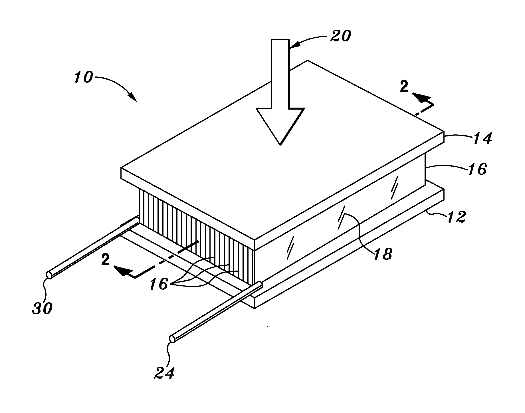
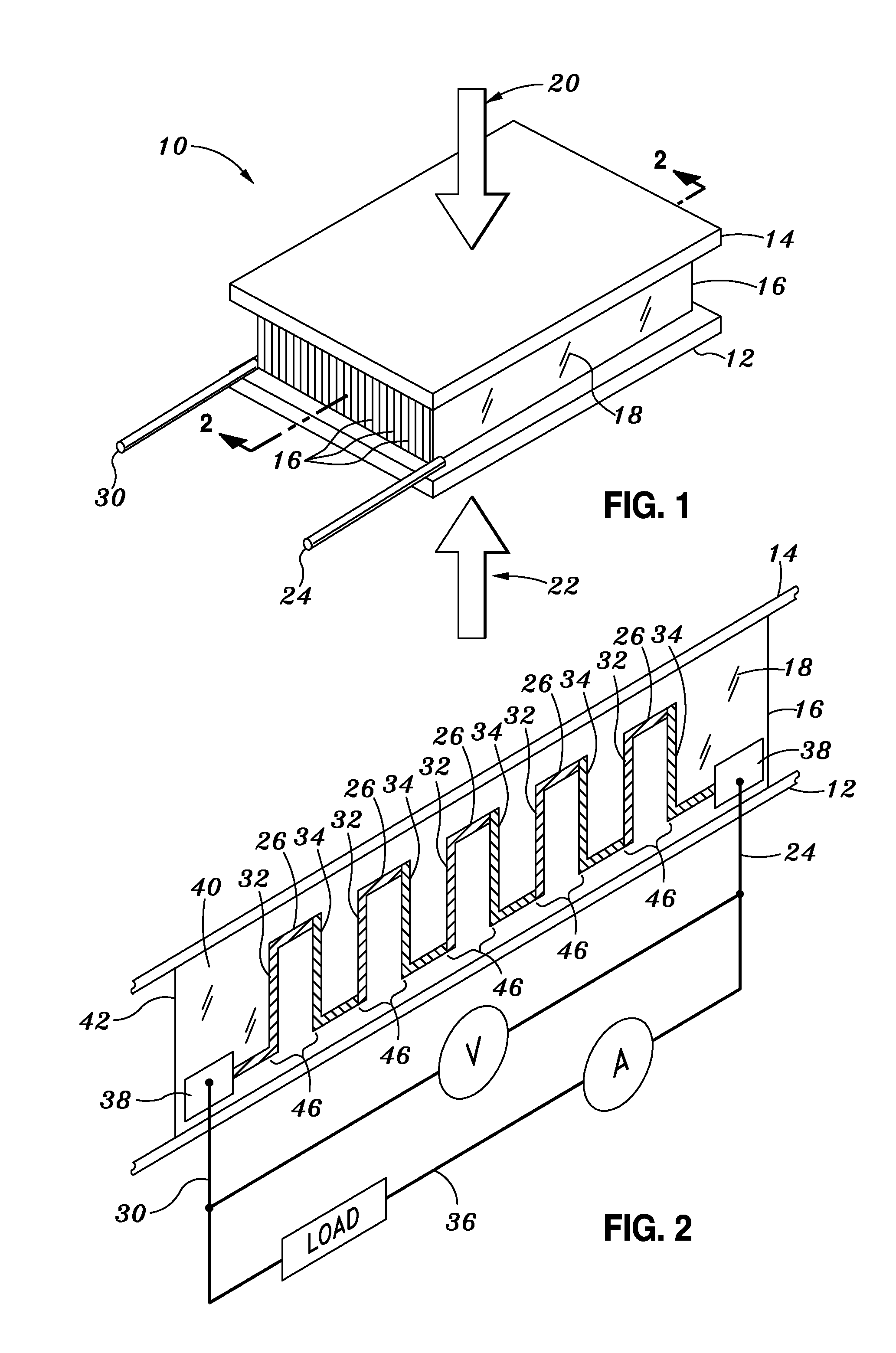
[0043]Referring now to the drawings wherein the showings are for purposes of illustrating preferred embodiments and not for purposes of limiting the same, FIG. 1 is a perspective view of an embodiment of a thermoelectric generator 10 having a generally square-shaped and being comprised of a rectangular array of foil segments 16 in a vertically stacked arrangement.

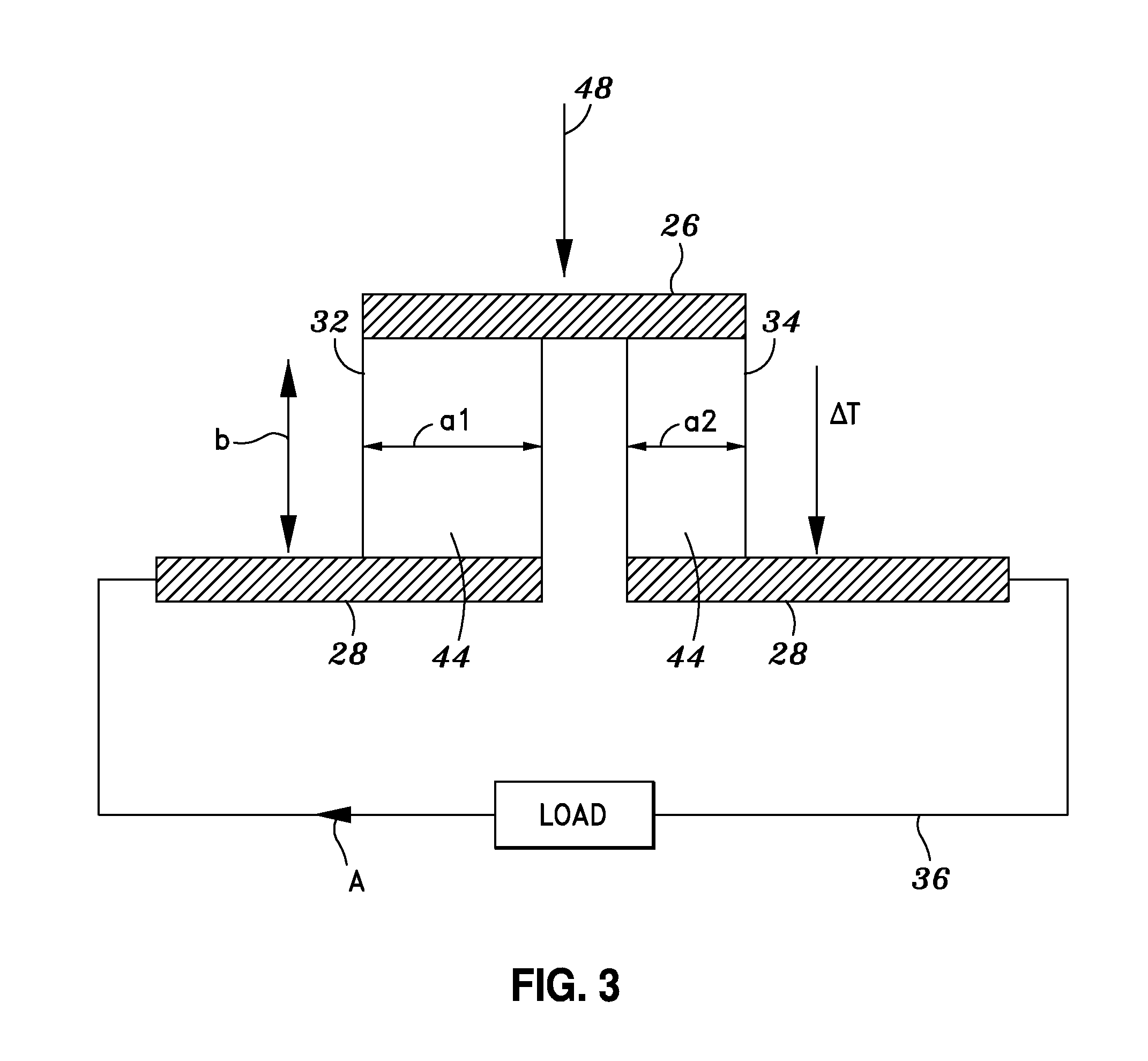
[0044]The embodiment shown in FIG. 1 is the subject of U.S. patent application Ser. No. 11 / 185,312 entitled LOW POWER THERMOELECTRIC GENERATOR and filed on Jul. 20, 2005, and U.S. Pat. No. 6,958,443 filed on May 19, 2003 and entitled LOW POWER THERMOELECTRIC GENERATOR, the entire contents of each being expressly incorporated by reference herein in their entirety and each having the same assignee as the present application. FIG. 2 is a cross-sectional side view of the thermoelectric generator shown in FIG. 1 illustrating the arrangement of alternating n-type and p-type thermoelectric legs that are disposed on a substrate fil...


PUM


Abstract

A thermoelectric generator has a top plate disposed in spaced relation above a bottom plate. A series of foil segments are electrically and mechanically connected end-to-end to generate a foil assembly that is spirally wound and in thermal contact with the bottom and top plates. Each foil segment comprises a substrate having a series of spaced alternating n-type and p-type thermoelectric legs disposed in parallel arrangement on the front substrate surface. Each of the n-type and p-type legs is formed of a bismuth telluride-based thermoelectric material having a thickness of about 10-100 microns, a width of about 10-100 microns and a length of about 100-500 microns. The alternating n-type and p-type thermoelectric legs are electrically connected in series and thermally connected in parallel such that a temperature differential between the bottom and top plates results in the generation of power.

Description

CROSS-REFERENCE TO RELATED APPLICATIONS[0001]The present application is a continuation-in-part application of pending U.S. patent application Ser. No. 11 / 185,312 entitled LOW POWER THERMOELECTRIC GENERATOR and filed on Jul. 20, 2005, which is a continuation of U.S. patent application Ser. No. 10 / 440,992 entitled LOW POWER THERMOELECTRIC GENERATOR and filed on May 19, 2003, now U.S. Pat. No. 6,958,443, the entire contents of each being expressly incorporated by reference herein.STATEMENT RE: FEDERALLY SPONSORED RESEARCH / DEVELOPMENT[0002](Not Applicable)BACKGROUND OF THE INVENTION[0003]The present invention pertains generally to thermoelectric devices and, more particularly, to a self-sufficient, low power thermoelectric generator having a compact size and a relatively high voltage output which is specifically adapted to be compatible with microelectronic devices.[0004]The increasing trend toward miniaturization of microelectronic devices necessitates the development of miniaturized p...

Claims


Application Information

Patent Timeline
Patent Type & Authority Applications(United States)
IPC IPC(8): H01L35/30
CPCH01L35/34H01L35/32H10N10/01H10N10/17
Inventor STARK, INGO
Owner DIGITAL ANGEL CORP
Why Eureka
Try Eureka