Inner-rotor-type brushless motor having built-in bus bar

a brushless motor and bus bar technology, applied in synchronous motors, dynamo-electric machines, electrical apparatus, etc., can solve the problems of increasing the size of the motor, increasing the cost and the number of manufacturing steps, and the sensor encountering difficulty in achieving high sensing accuracy, so as to improve the reliability of the sensor against current heat, reduce the size of the brushless motor, and prevent the effect of torque drop and torque ripple due to deteriorated sensor waveform

Inactive Publication Date: 2009-01-29
MABUCHI MOTOR
View PDF7 Cites 48 Cited by
  • Summary
  • Abstract
  • Description
  • Claims
  • Application Information

AI Technical Summary

Benefits of technology

[0015]According to the present invention, the size of the brushless motor can be reduced by means of mounting the sensor onto the bus bar. In addition, since the sensor is separated from the heat generating portion of the bus bar, even when copper bars or connection terminals incorporated into th

Problems solved by technology

The disclosed motor has a problem in that the bus bar and the sensor component individually arranged in the thrust direction increases the entire length of the motor, to thereby increase the size of the motor.
Further, since the sensor must be attached to the housing, the number of components increases, thereby increasing cost and the number of manufacturing steps.
In addition, the disclosed motor has a structure in which the number of cumulative errors increases, and thus, the sensor encounters difficulty in attaining high sensing accuracy.
Such a structure decreases

Method used


Image

  • Inner-rotor-type brushless motor having built-in bus bar
  • Inner-rotor-type brushless motor having built-in bus bar
  • Inner-rotor-type brushless motor having built-in bus bar

Examples


Embodiment Construction

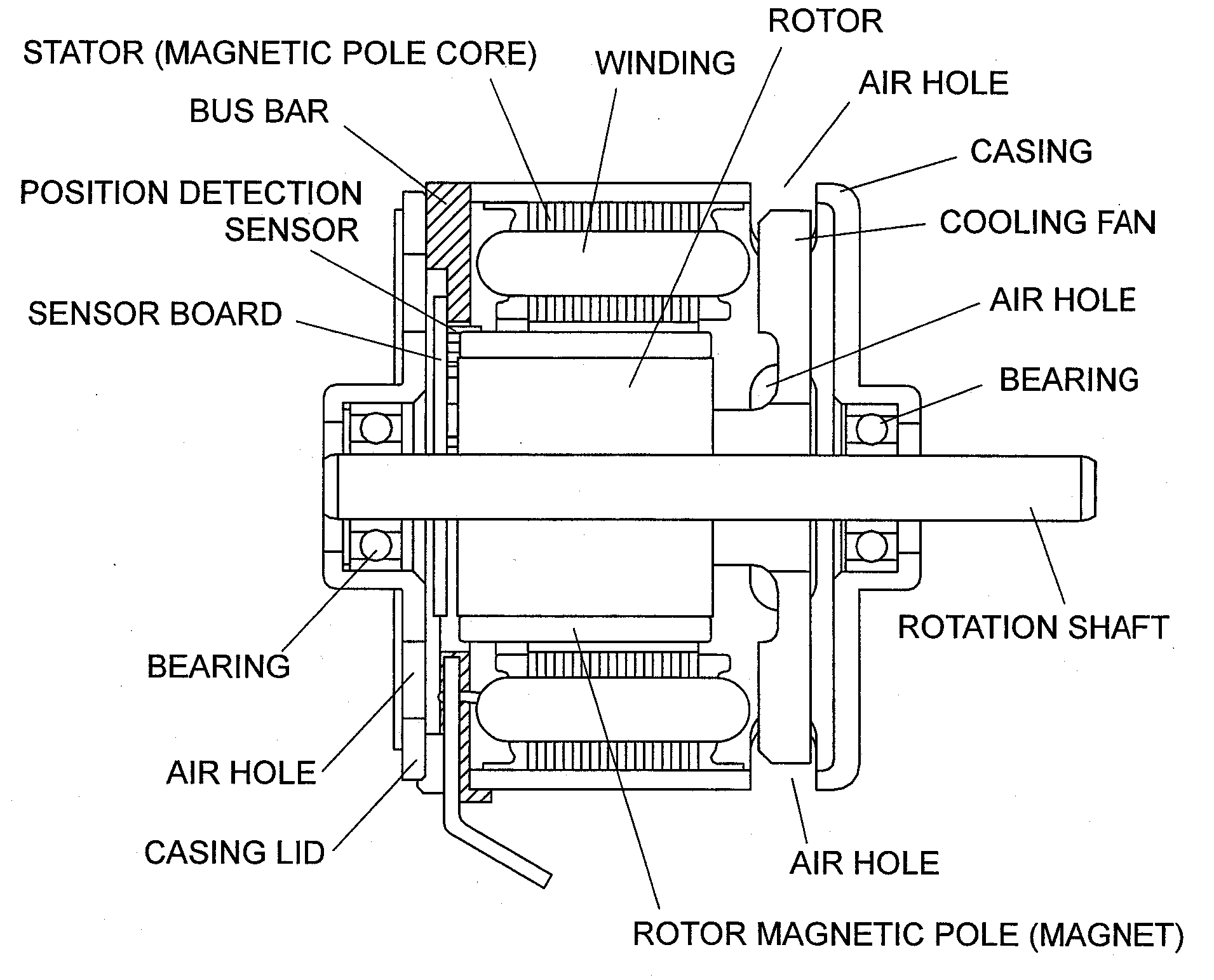
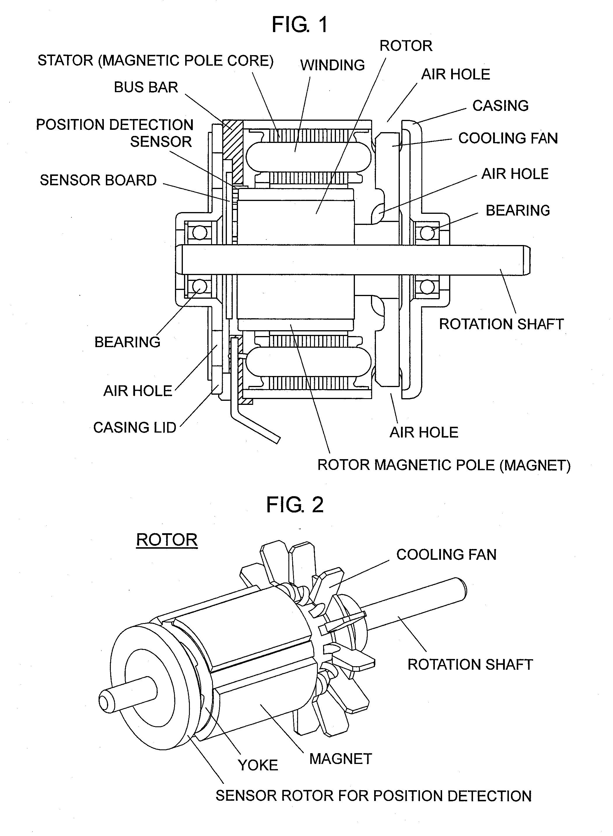
[0029]The present invention will now be described by way of examples. FIG. 1 is a cross sectional view showing the overall structure of an inner-rotor-type brushless motor which embodies the present invention. A motor housing is composed of a bottomed, hollow cylindrical casing formed of a metal or a resin, and a casing lid formed of a metal or a resin and attached to the opening portion of the cylindrical casing. A stator is fixed to the inner wall surface of the cylindrical casing. The stator includes a magnetic pole core, and coils wound around the core via an insulating means such as an insulator. Bearings for supporting a rotation shaft of a rotor are fixedly accommodated in central portions of the casing bottom portion and the casing lid. One end of the shaft projects from the casing bottom portion toward the outside of the motor housing, and an external apparatus to be driven is connected to the projecting end.

[0030]In the brushless motor shown in FIG. 1, a cooling fan is fix...


PUM


Abstract

An inner-rotor-type brushless motor includes a bus bar which connects together U-phase, V-phase, and W-phase windings and connects them to output wires. The bus bar includes, as conductive members, three external terminals connected to first ends of the windings and one Y-connection terminal for connecting second ends of the windings together. The external terminals and the Y-connection terminal are disposed on the body of the bus bar such that the Y-connection terminal and the external terminals are located on one side on the circumference of the bus bar body, whereby the bus bar body has a circumferential region where the conductive members are not present. A sensor bard carrying a position detection sensor is attached the bus bar body such that the position detection sensor is located in the circumferential region where the conductive members are not present.

Description

BACKGROUND OF THE INVENTION[0001]1. Field of the Invention[0002]The present invention relates to an inner-rotor-type brushless motor in which a sensor board for detecting rotation of a rotor is attached to a bus bar which connects together U-phase, V-phase, and W-phase windings wound on a stator magnetic pole core and connects them to output wires.[0003]2. Description of the Related Art[0004]In an inner-rotor-type brushless motor, a sensor attached to a stator detects magnet poles provided on the rotor side so as to switch and control currents supplied to stator windings. When such a brushless motor is used for driving electrical tools or other electrical equipment which requires supply of relatively large current to the motor, a bus bar has conventionally been used for connecting wiring from an external power source to the windings.[0005]The brushless motor is configured such that the bus bar attached to the stator and the sensor for rotation detection are individually arranged in ...

Claims


Application Information

Patent Timeline
IPC IPC(8): H02K11/00H02K19/10
CPCH02K3/522H02K29/08H02K2211/03H02K2203/09H02K2203/03
Inventor KINOSHITA, NOBUOMATSUOKA, YUICHIRO
Owner MABUCHI MOTOR
Why Eureka
Try Eureka