Field controllable rotating electric machine system with flux shunt control

a technology of electric machine and flux shunt, which is applied in the direction of electric generator control, magnetic body, dynamo-electric converter control, etc., can solve the problems of large energy loss, difficult control of the system, and inability to obtain optimal power in a wide rotational speed range. achieve the effect of field weakening control

Inactive Publication Date: 2009-01-29
KURA LAB
View PDF8 Cites 15 Cited by
  • Summary
  • Abstract
  • Description
  • Claims
  • Application Information

AI Technical Summary

Benefits of technology

[0012]Accordingly, an embodiment of the present invention advantageously provides a method for controlling a magnetic field strength, a rotating electric machine apparatus, and a rotating electric machine system, by which field-weakening control becomes easy, while satisfying the following conditions: (1) mechanical means are adopted for maintaining the operating condition; (2) generation of a magnetic force disturbing operation of the mecha...

Problems solved by technology

However, in both electric motors and electric generators, optimum power is not always obtained in a wide rotational speed range because of constant magnetic field strength from the field magnet.
In the case of the electric motor, the control thereof becomes difficult in a high-speed rotational region because the back electromotive force (power generation voltage) becomes too high, and therefore, various methods for weakening the field strength as field-weakening control have been proposed.
In the electric motor, field-weakening control by current phase control has been widely adopted, but energy loss is large because current flows that does not directly contribute to the rotation.
When current excitation for the control is used with a permanent magnet excitation, the structure of the rotating electric machine becomes complex and additionally ...

Method used


Image

  • Field controllable rotating electric machine system with flux shunt control
  • Field controllable rotating electric machine system with flux shunt control
  • Field controllable rotating electric machine system with flux shunt control

Examples


first embodiment

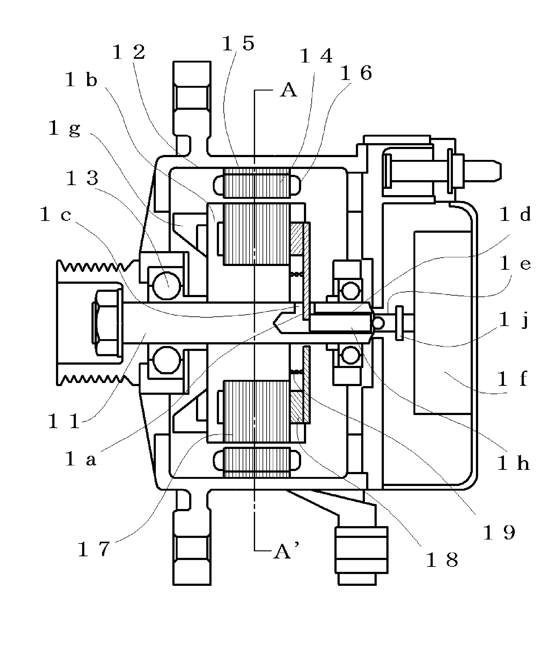
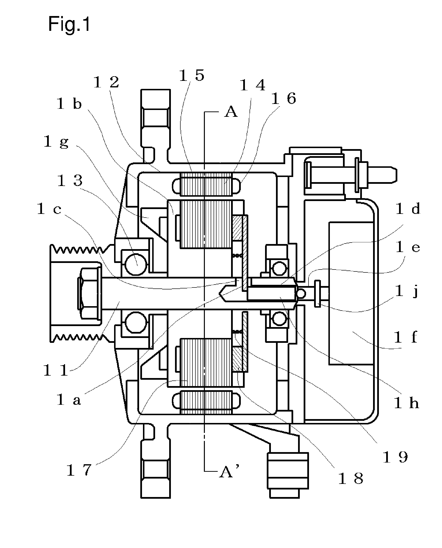
[0097]As described above, in the rotating electric machine apparatus shown in FIGS. 1 to 7, it has been explained that by displacing the magnetic excitation part 18 axially, the magnetic flux flowing in the armature can be controlled. The first embodiment is a system for optimizing the output by controlling the magnetic flux amount, and the control method as the rotating electric machine system will be explained by using FIG. 8.

[0098]FIG. 8 shows a block diagram of the rotating electric machine system for controlling the field strength. In FIG. 8, the rotating electric machine apparatus 81 has an input 82 and an output 83, and a control device 85 controls the field strength of the rotating electric machine apparatus 81 through a control signal 86 referring to an output 83 of the rotating electric machine apparatus 81 and a state signal 84 including positions of the magnetic excitation part 18 that are in the movable magnetic pole part. The number 87 represents a driving circuitry of...

second embodiment

[0142]As described above, in the rotating electric machine apparatus shown in FIGS. 9 to 13, it has been explained that by relatively displacing the surface magnetic pole part 94 with respect to the magnetic excitation part 93, the magnetic flux flowing through the main magnetic flux pathway can be controlled at almost 100%, and furthermore, the means and the method for above displacement have been explained. The second embodiment is a system for optimizing the output by controlling the magnetic flux flowing through the main magnetic flux pathway like a sampling servo, and the control method as the rotating electric machine system will be explained by using FIGS. 8 and 14.

[0143]FIG. 8 shows a block diagram of the rotating electric machine system for controlling the field strength. FIG. 14 shows the timing chart which controls the torque of an electric motor and controls the generated voltage of an electric generator by controlling the surface magnetic pole part 94 displacement in sa...

third embodiment

[0169]As described above, in the rotating electric machine apparatus shown in FIGS. 15 to 17, it has been explained that by relatively displacing the surface magnetic pole part 94 with respect to the magnetic excitation part 93, the magnetic flux flowing through the main magnetic flux pathway can be controlled at almost 100%, and furthermore, the means and the method for above displacement have been explained. The third embodiment is a system for optimizing the output by controlling the magnetic flux flowing through the main magnetic flux pathway, and the control method as the rotating electric machine system will be explained by using FIG. 8.

[0170]A rotating electric machine system in which the rotating electric machine apparatus serves as an electric motor and by which the field-weakening control is performed to optimize the rotational force control will be explained.

[0171]When the rotational speed that is the output 83 becomes larger than a predetermined value and the magnetic fl...


PUM


Abstract

In a magnet-exciting rotating electric machine, a magnetic field pole part opposing an armature is composed to be divided into a surface magnetic pole part and a magnetic excitation part so as to be capable of being relatively displaced. The magnetic excitation part supplies a magnetic flux to a magnetic salient pole. The magnetic flux from the field magnet is divided into a main magnetic flux pathway that circulates through the armature side and a bypass magnetic flux pathway that does not pass through the armature, and thereby, the magnetic flux of the main magnetic flux pathway is changed. The magnetic resistances of the main magnetic flux pathway and the bypass magnetic flux pathway are composed so that total magnetic flux amount from the field magnet is maintained constant, and then a magnetic force preventing the relative displacement is maintained small.

Description

CROSS-REFERENCE TO RELATED APPLICATIONS[0001]The present application claims priority under 35 U.S.C. §119 to Japanese Patent Applications No. 2007-194043 filed Jul. 26, 2007, No. 2007-212690 filed Aug. 17, 2007, No. 2007-279975 filed Oct. 29, 2007, No. 2007-280003 filed Oct. 29, 2007, and No. 2007-313140 filed Dec. 4, 2007. The contents of these applications are incorporated herein by reference in their entirety.BACKGROUND OF THE INVENTION[0002]1. Field of the Invention[0003]The present invention relates to rotating electric machines such as electric generators and electric motors having a permanent magnet.[0004]2. Description of the Related Art[0005]Rotating electric machine apparatuses, such as an electric generator for generating electric power electromagnetically by relative rotation between a permanent magnet and an armature, or an electric motor for generating relative rotation between a permanent magnet and an armature by interaction between the permanent magnet and a magneti...

Claims


Application Information

Patent Timeline
IPC IPC(8): H02K21/28H01F13/00
CPCH02K21/029H02K21/028
Inventor ICHIYAMA, YOSHIKAZU
Owner KURA LAB
Why Eureka
Try Eureka